ELECTRICAL SYSTEM
10G-16
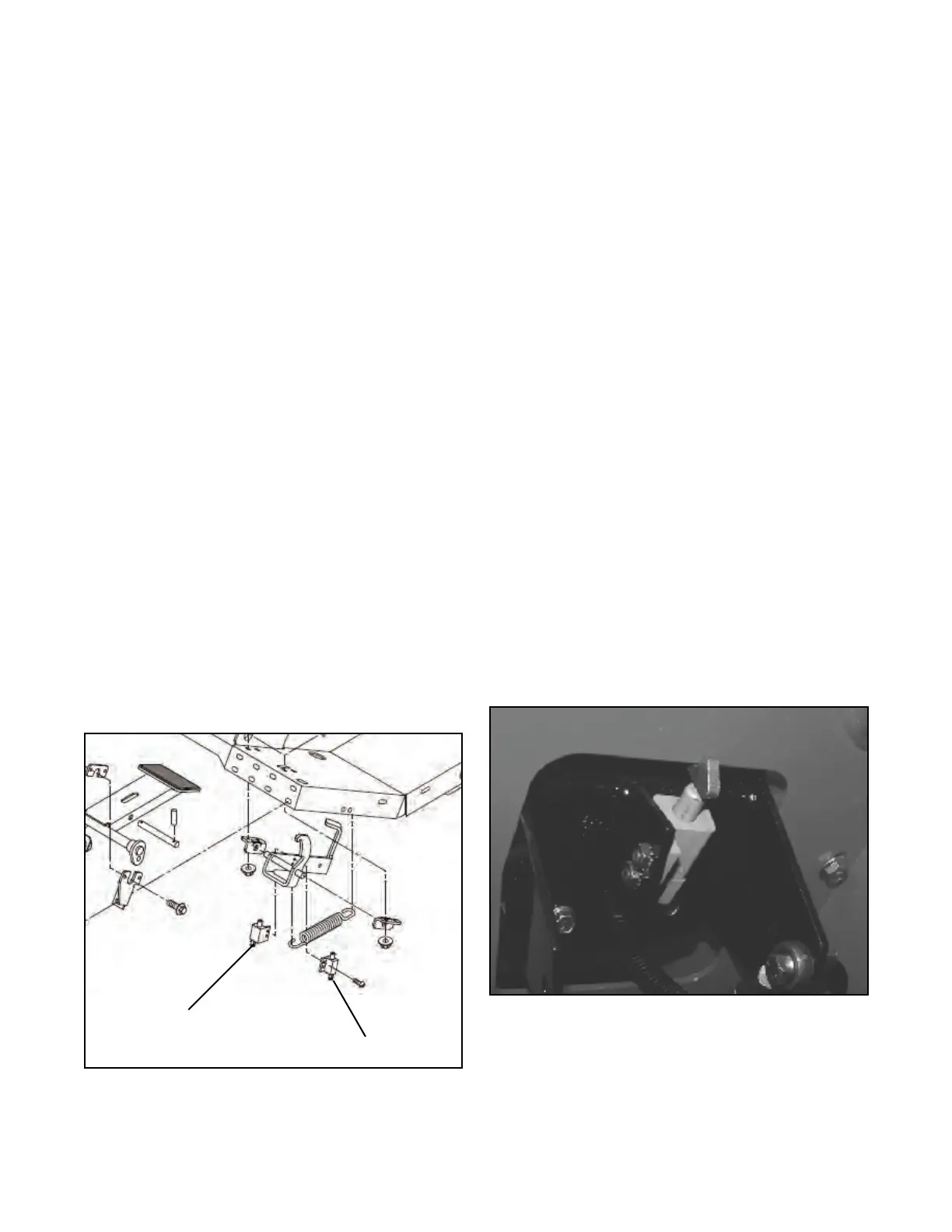
PARKING BRAKE SWITCHES (SW5
& SW11)
General
The parking brake switches (Figure 10G-4) are a single
pole normally open (SPNO) switch, which means no
current can travel through the switch until activated.
When the switch is mechanically actuated (depressed)
by the brake pedal, a set of contacts are closed, creat-
ing a path for the movement of current through the
switch. During the test it must be determined if the
switches close (continuity) when depressed.
Continuity Test
1. Shut down the engine and remove the ignition
key.
2. Set the multimeter to the continuity scale.
3. Connect one test lead to a connector plug socket
and the other test lead in the other plug socket.
Continuity should not be available when the switch
plunger is fully extended.
4. Connect one test lead to a connector plug socket
and the other test lead in the other plug socket.
Actuate the switch by depressing the plunger.
5. Continuity should be available and resistance indi-
cating 0 to 0.5 (Ohms) while the switch plunger
is depressed.
Figure 10G-4. Park Brake Switches
NEUTRAL SWITCH (SW3)
General
The neutral switch (Figure 10G-5) is a double pole nor-
mally closed (DPNC) switch, which means current can
travel through the switch until the switch is depressed.
When the switch is mechanically actuated (depressed)
by the traction pedal latch, the switch opens preventing
current flow through the switch. During the test it must
be determined if the switch closes (continuity) when the
traction pedal latch is released and if the switch opens
when the traction pedal latch is depressed.
Continuity Test
1. Shut down the engine and remove the ignition
key.
2. Set the multimeter to the continuity scale.
3. Connect one test lead to a pole on the switch and
the other test lead to the other pole.
Continuity should be available with the switch
plunger extended and the traction pedal latch
released.
Continuity should not be available with the switch
plunger depressed by the traction pedal latch.
See SECTION 2 for switch adjustment proce-
dures.
Figure 10G-5. Neutral Switch
SW11 - Parking Brake Interlock
SW5 - Parking Brake Switch
 Loading...


