ELECTRICAL SYSTEM
10G-19
DIFFERENTIAL LOCK SWITCH
(SW9) - OPTIONAL
General
The foot switch is a single pole normally open (SPNO)
momentary switch, which means no current can travel
through the switch until activated. When the switch is
actuated (depressed) by the operator, a set of contacts
is closed. This creates a path for the movement of cur-
rent through the switch. During the test, it must be
determined if the switch closes (continuity) when
depressed.
1. Shut down the engine and remove the ignition
key.
2. Disconnect the ground (black) NEG battery cable
from the battery.
3. Disconnect the wire harness connector from the
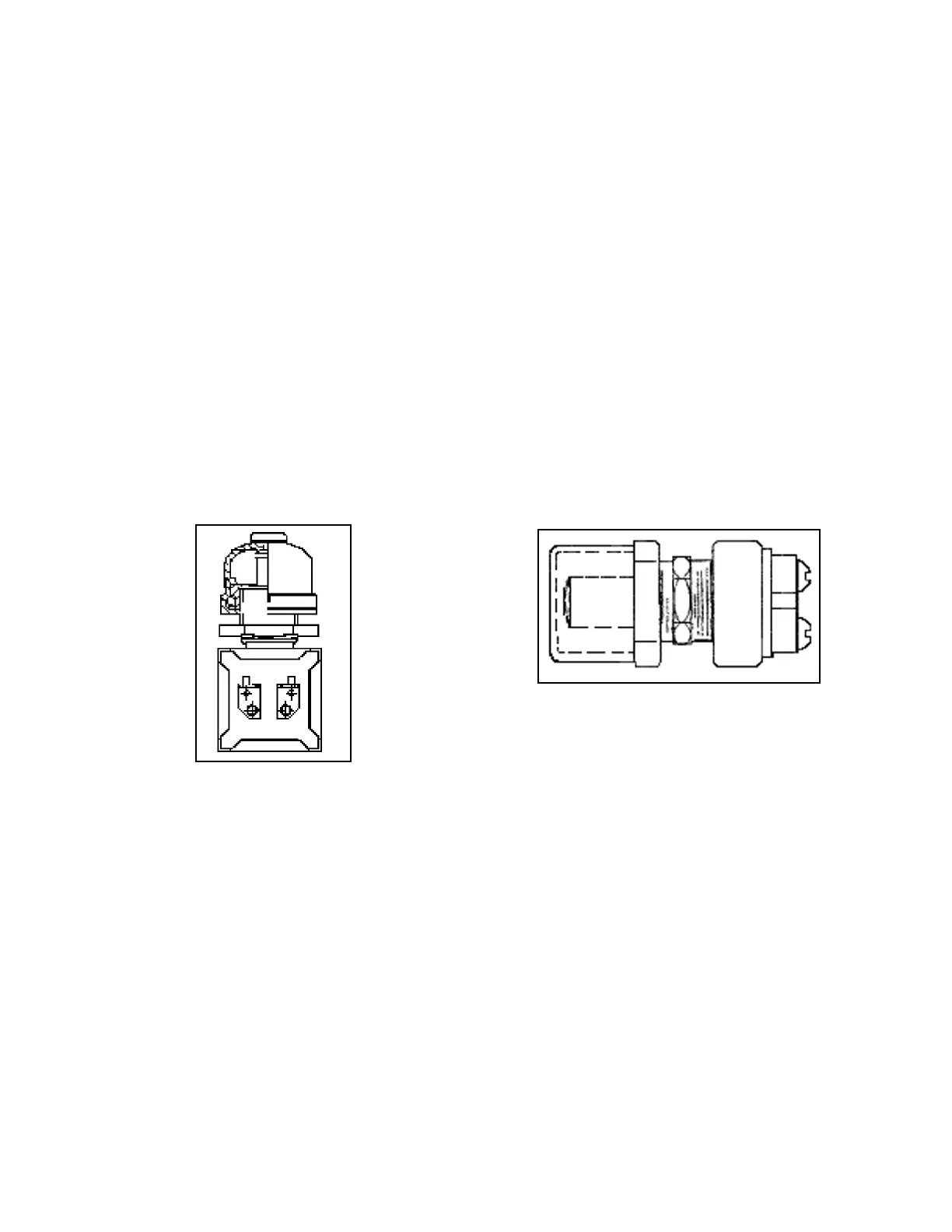
switch (Figure 10G-11).
Figure 10G-11. Foot Switch
4. Set the multimeter to the continuity scale.
5. Connect one test lead to one of the switch termi-
nals, and connect the other test lead to the other
switch terminal.
Continuity should not be available when the switch
plunger is fully extended.
Continuity should be available by manually
depressing the switch plunger, and resistance
should be less than 0.5 (Ohms).
6. Restore all electrical connections.
HORN SWITCH (SW8) - OPTIONAL
General
The horn switch is a single pole normally open (SPNO)
switch, which means no current can travel through the
switch until activated. When the switch is mechanically
actuated (depressed) by the operator, a set of contacts
is closed. This creates a path for the movement of cur-
rent through the switch. During the test, it must be
determined if the switch closes (continuity) when
depressed.
1. Shut down the engine and remove the ignition
key.
2. Disconnect the ground (black) NEG battery cable
from the battery.
3. Remove the steering tower cover.
4. Disconnect the wire harness connector from the
horn switch (Figure 10G-12).
Figure 10G-12. Horn Switch
5. Set the multimeter to the continuity scale.
6. Connect one test to one of the switch terminals
and connect the other test lead to the other switch
terminal.
Continuity should not be available when the switch
plunger is fully extended.
Continuity should be available by manually
depressing the switch plunger, and resistance
should be less than 0.5 (Ohms).
7. Restore all electrical connections and replace the
steering tower cover.
 Loading...


