ELECTRICAL SYSTEM
10H-21
SECTION 10H. SENDERS
GENERAL
Senders are used to activate a light or gauge to warn
the operator of a condition in the engine. A temperature
sender monitors engine coolant temperature and dis-
plays the result on a temperature gauge. An oil sender/
switch monitors the engine oil pressure and illuminates
a warning light to warn the operator when the oil pres-
sure drops to a critical level.
COOLANT TEMPERATURE SENDER
TEST (R2)
The temperature sender is a rheostat located on the
alternator side of the engine at the thermostat housing.
As the temperature rises, resistance in the sender
decreases, creating a ground and drawing the temper-
ature gauge indicator to the hot side. The sender resis-
tance range is 33 (Ohms) to 240 (Ohms).
Test the temperature sender as follows:
1. Shut down the engine and remove the ignition
key. Allow the engine to cool completely.
2. Remove the wiring harness connector from the
end of the sender.
3. Set the multimeter to the 2K scale.
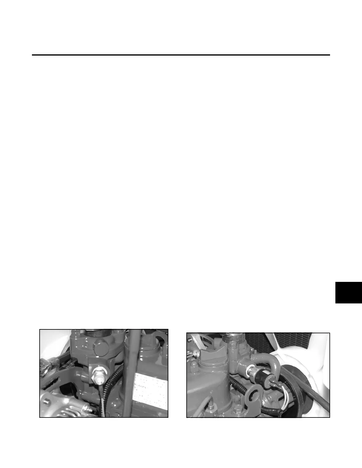
4. Place one test lead on the sender wiring harness
connector stud. Place the other test lead on the
base of the sender (Figure 10H-1).
When cold, sender resistance should be high
between the connector stud and base.
When hot, sender resistance should be low
between the connector stud and base.
Figure 10H-1. Coolant Temperature Sender
COOLANT TEMPERATURE SWITCH
TEST (SW6)
The temperature switch is located on the injection
pump side of the engine in the thermostat housing. The
temperature switch triggers an alarm and shuts off the
cutter deck when the engine overheats. The switch is a
normally open switch and closes when the engine tem-
perature exceeds 220°F (104°C).
1. Shut down the engine and remove the ignition
key. Allow the engine to completely cool.
2. Install a jumper wire onto the sender terminal and
ground the other end of the jumper. Turn the key
to position 1; the horn should be audible.
3. Remove the wiring harness connector from the
end of the temperature switch.
4. Set the multimeter to the continuity scale.
5. Place one test lead on the sender terminal. Place
the other lead on the base of the sender.
6. When the engine temperature is below 220°F
(104°C) there should not be continuity between
the connector and the base.
7. Drain the engine coolant and remove the tempera-
ture switch from the engine.
8. The element of the temperature switch must be
heated to 220°F (104°C).
9. Place one test lead on the sender terminal. Place
the other lead on the base of the sender.
10.There should be continuity between the connector
and base of the temperature switch.
Figure 10H-2. Temperature Switch
10H
 Loading...


