ELECTRICAL SYSTEM
10I-25
SECTION 10I. RELAYS AND SOLENOIDS
RELAYS (K1- K5)
Relays are electromechanical devices that control the
transmission of electrical current with a circuit. A sche-
matic of the internal movement of the relay is printed
on the relay itself. The relays used in the electrical sys-
tem all use the same NO (normally open) configuration,
except the deck valve relay, which is in the normally
closed configuration.
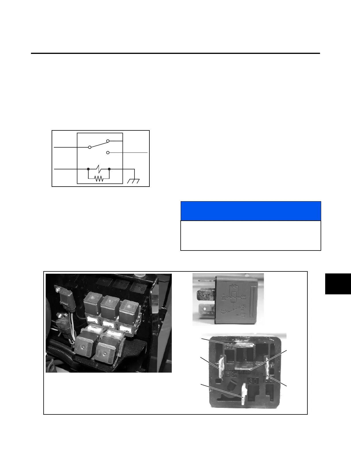
Figure 10I-1. Relay Circuit
Pole 85, as shown in Figure 10I-1, is a grounded termi-
nal. When current is applied to pole 86, the coil circuit
between the poles is completed and a magnetic action
draws the switch lever at pole 87A to pole 87, closing
the relay and allowing current to flow from pole 30 (the
input power source) to pole 87 (the output power con-
nection).
Relay Test
Check the relays for proper operation as follows:
1. Remove the relay from the relay box.
2. Set the multimeter to the continuity scale.
3. Place one test lead on pole 30 and one test lead
on pole 87A.
Continuity should be available between poles 30
and 87A.
4. Using a 12-volt DC power source, apply the
ground side to pole 85 and 12 VDC to pole 86. At
the same time check for continuity between poles
30 and 87.
There should be an audible “click” when current is
applied and continuity should be available
between poles 30 and 87.
Replace a relay that does meet the above test results.
Figure 10I-2. Relays
30
8586
87
87A
NOTICE
If the relay responds as described in the above test,
the circuit problem may be in the power supply to the
relay. Using the electrical schematics in Section 10M
and a multimeter, check the relay pole circuits.
Electrical Schematic
Symbol Designation “K”
Relay Circuit
87A
85
87
86
30
10I
 Loading...


