BRAKE SYSTEM
5C-6
Disassembly
1. Using a suitable jack, lift the front wheels off the
ground. Support the tractor with jack stands.
2. Release the parking brake.
3. Remove the return spring (Figure 5C-1).
4. Remove the rod linkage from the actuating lever.
5. Remove the drum nut and the brake drum.
6. Remove the holding springs, brake shoes, and
tension springs from the brake housing
(Figure 5C-2).
Figure 5C-2. Brake Housing Assembly
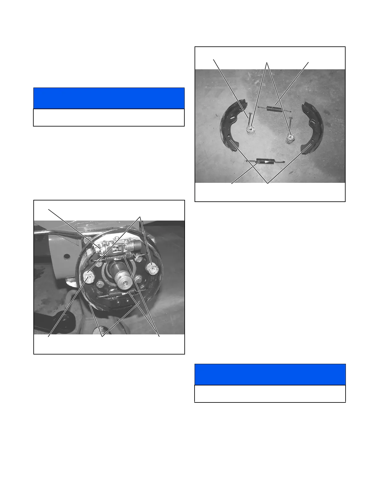
Inspection and Cleaning
1. Remove brake dust, dirt, and debris from the
brake housing and drum.
2. Inspect the brake shoes, holder springs, holder
pins, and tension springs for wear and distortion.
Replace as necessary (Figure 5C-3).
Figure 5C-3. Brake Components
3. Inspect the parts listed below for wear and distor-
tion. Replace as necessary.
• Actuating lever
• Return spring
• Rod linkage
•Pivot rod
4. Inspect the brake drum for grooves, excessive
wear, and damage. Replace the brake drum as
necessary.
Assembly
1. Install the brake shoes, tension springs, and hold-
ing springs.
2. Install the brake drum. If necessary, set the adjust-
ing pin (Figure 5C-3) to allow for sufficient clear-
ance between the brake drum and brake shoes.
3. Install the drum nut and tighten nut to 250 ft-lbs
(339 Nm).
4. Install the rod linkage and return spring.
NOTICE
Removing the wheels allows access to the brake
assembly.
Holding
Pin
Adjusting
Pin
Brake
Shoes
Tension
Springs
Holding
Springs
NOTICE
Pin adjustment should be made to allow for minimal
clearance between the brake drum and brake shoes.
Brake
Shoes
Upper Tension
Spring
Lower Tension
Spring
Holding
Pin
Holding
Springs
 Loading...


