HYDROSTATIC POWER TRAIN
4252490-Rev A 5-51
5
Figure 5-51
NOTES
• Label all hydraulic hoses and fittings before
disconnecting to ensure correct installation.
• Close all openings with caps or plugs to prevent
contamination.
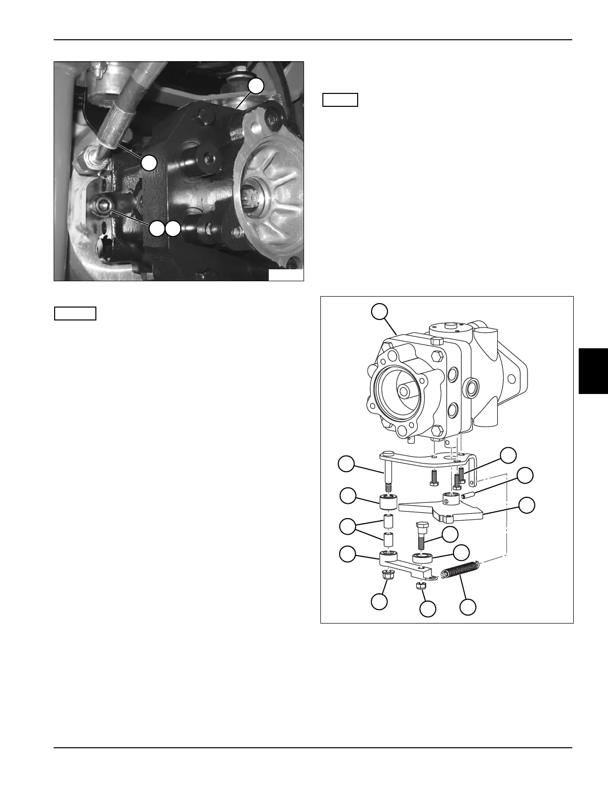
12. Disconnect hose (14).
13. Support traction pump (11) with a suitable lifting
device.
14. Remove mounting screw (12) and lock washer (13)
on each side of traction pump (11).
15. Remove traction pump (11).
Installation Notes
• Install traction pump by reversing the order of
removal.
• Ensure new O-rings are in place before installing
hoses on fittings.
• Pressure filter the traction system. (See “Portable
In-Line Filter” on page 5-5.)
• Refill hydraulic oil tank. (Refer to “Parts and
Maintenance Manual” for correct oil specifications.)
• Start engine. Check for leaks and repair as
necessary.
• Perform neutral adjustment. (See “Neutral
Adjustment” on page 5-32.)
Disassembly, Inspection, and Assembly
See Figures 5-52 through 5-54.
NOTE
Service to the traction pump is limited to the following
components:
• Charge Pump
• Implement Relief Valve
• Charge Relief Valve
• Trunnion and Shaft Seals
Damage or excessive wear to traction pump components
other than service components requires traction pump
replacement.
Control Linkage and Fittings
1. Thoroughly clean the exterior of the pump housing
before disassembly.
Figure 5-52
2. Disconnect spring (7) from control weldment (13).
14
TN3869
13
11
12
1 Traction Pump 6 Bearing 10 Roller Arm
2 Screw (3) 7 Spring 11 Bushing (2)
3 Roll Pin 8 Lock Nut 12 Roller
4 Cam Plate 9 Lock Nut 13 Control Weldment
5Eccentric
Screw
TN3908
7
8
1
3
9
6
5
11
10
4
12
13
2

 Loading...


