Adjustment of the grating disc
11/2020 243343V03_EN 47
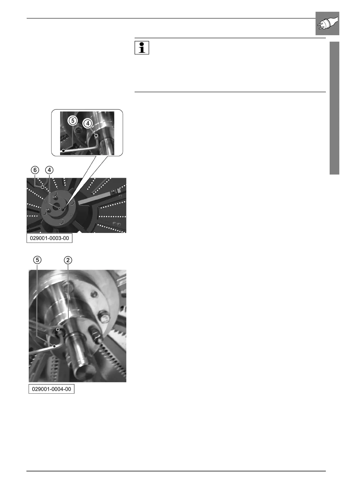
b Adjust the distance to the matrix frame by turning the grub screws (4,
3 pieces). Use a 4 mm Allen key (5) for this.
b Turn the grub screw (4) anticlockwise to reduce the distance between
the matrix frame and the grating disc.
b Turn the grub screw (4) clockwise to increase the distance between
the matrix frame and the grating disc.
b Tighten the central lock of the grating disc.
b Turn the grating disc. Check the uniformity of the adjustments by turn-
ing the grating disc by hand. Use the handles (6) for this.
b Correct adjustment means that the gap between the grating disc and
the matrix frame is between +0.1 and + 0.4 mm.
Use a feeler gauge for the check.
b If the adjustment is not OK, repeat the procedure from Step 3, other-
wise perform the next step.
b After completion of the adjustment, lock the grub screws as shown in
the picture. Hold the grub screw steady using an Allen key (5) to tighten
the lock nuts (2).
b Then screw on the cap nuts again and tighten these.
b Refer to the chapter Outer Setting for the activities for fine adjustment
of the cutting gap and the evenness.
Note:
The three grub screws are only used as limit stop. The disc
does not move until tightening of the central lock.
This means you cannot check the cutting gap until the central
lock is tightened (by turning to the left, anticlockwise).
Adjust the grub screws dimensionally equal to obtain an optimal
cutting result.