Motion Coordinator Technical Reference Manual
Expansion Modules 5-5
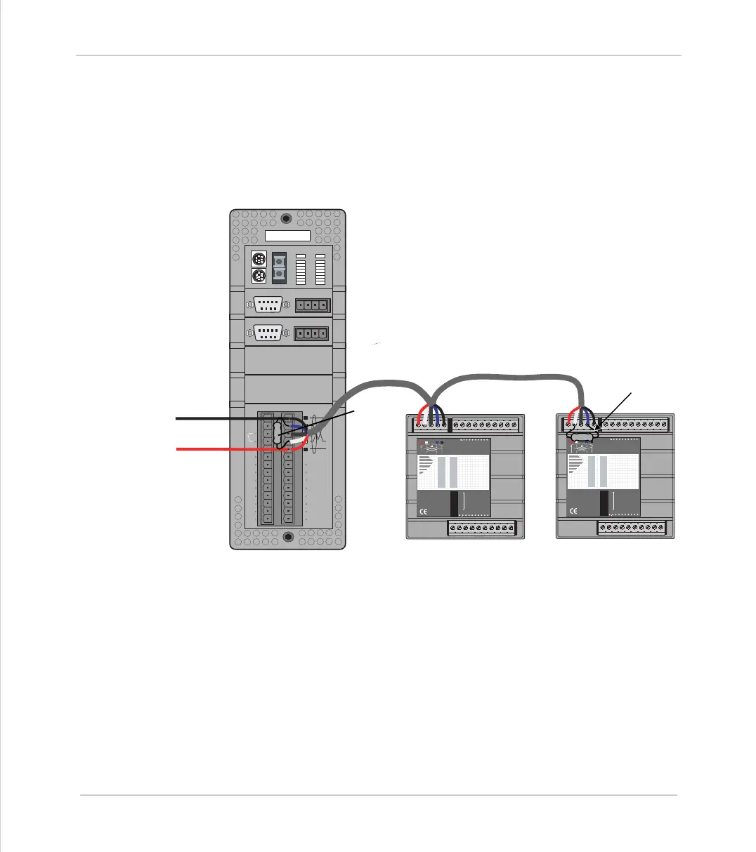
Input/Output Modules
Bus Wiring
The CAN 16-I/O Modules and the Motion Coordinator are connected together on a
network which matches the physical specification of DeviceNet running at
500kHz. The network is of a linear bus topology. That is the devices are daisy-
chained together with spurs from the chain. The total length is allowed to be up
to 100m, with drop lines or spurs of up to 6m in length. At both ends of the net-
work, 120 Ohm terminating resistors are required between the CAN_H and CAN_L
connections. The resistor should be 1/4 watt, 1% metal film.
The cable required consists of:
Blue/White 24AWG data twisted pair
+ Red/Black 22AWG DC power twisted pair
+ Screen
A suitable type is Belden 3084A.
P165
0
1
2
3
4
5
6
7
8
9
10
11
12
13
14
15
1
2
4
8
16
32
OFF
MS NS
PR
DR
10 11 12 13 14 15 24v Ov98
NODE
ADDRESS
CAN 16-I/O
Trio
7654 32 1 00v 24v
P165
0
1
2
3
4
5
6
7
8
9
10
11
12
13
14
15
1
2
4
8
16
32
OFF
MS NS
PR
DR
10 11 12 13 14 15 24v Ov98
NODE
ADDRESS
CAN 16-I/O
Trio
7654 32 1 00v 24v
ENCODER
V+ V- R
0v
5 4 3 2 1
9 8 7 6
ENCODER
V+ V- R
0v
5 4 3 2 1
9 8 7 6
IO8
IO9
IO10
IO11
IO12
IO13
IO14
IO15
I 0
I 1
I 2
I 3
I 4
I 5
I 6
I 7
24v
0v
Trio
8
9
10
11
12
13
14
15
0
OK
NET
0
1
STATUS
1
2
3
4
5
6
7
120 ohm
Terminating
Resistor
120 ohm
Terminating
Resistor
24v Power Supply
to Network
 Loading...


