5-8 Expansion Modules
Input/Output Modules
Trio Motion Technology
LED Indicators
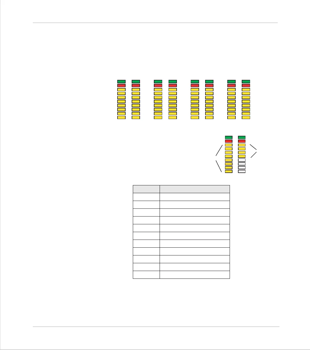
When NS is ON LEDs marked 0 - 15 represent the input channels 0 - 15 of the
module. The actual input as seen by the Motion Coordinator software will
depends on the I/O modules address:
Error Codes:
When an error occurs on a CAN I/O module,
the fault code is represented by a binary
number displayed on the leds.
Code Error Description
1
Invalid Protocol
2
Invalid Module Address
3
Invalid Data Rate
4
Uninitialised
5
Duplicate Address
6
Start Pending
7
System Shutdown
8
Unknown Poll
9
Poll Not Implemented
10
CAN Error
11
Receive Data Timeout
NS
24
25
26
27
28
29
30
31
16
17
18
19
20
21
22
23
MS
Address = 1
NS
40
41
42
43
44
45
46
47
32
33
34
35
36
37
38
39
MS
Address = 2
NS
56
57
58
59
60
61
62
63
48
49
50
51
52
53
54
55
MS
Address = 3
NS
72
73
74
75
76
77
78
79
64
65
66
67
68
69
70
71
MS
Address = 4
NS (OFF)
8
9
10
11
12
13
14
15
1
2
3
4
5
6
7
8
MS
Error Code
displayed on
IO 8 .. 11
Whole Bank
Flashing