Motion Coordinator Technical Reference Manual
Expansion Modules 5-7
Input/Output Modules
TRIO Protocol:
The switch marked PR is set ON to select the standard TRIO protocol.
The top 6 DIP switches on the CAN 16-I/O set the module address. Only addresses
0 - 15 are valid for CAN 16-I/O modules.
The switch marked DR sets the CAN Bus communications rate to 125kHz or
500kHz. Only 500Khz is valid with the TRIO protocol.
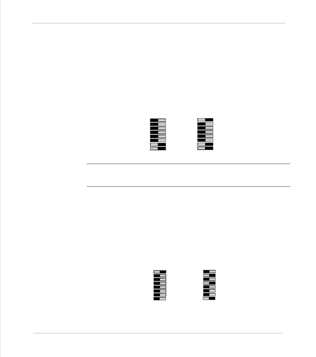
The addresses for I/O modules MUST be set in sequence, 0,1,2 etc. Therefore the
first two CAN 16-I/O Modules would have switch settings as shown below:
Note:
The I/O Channels referred to above start at 16. This is because the
numbering sequence starts with channels 0 - 15, which are on the Motion
Coordinator master unit itself.
LENZE Drive Protocol:
The switch marked PR is set OFF to select the LENZE protocol.
The top 6 DIP switches are used to set the drive number. This should be set to a
to 1..63. If the drive number is set to 0, the module will transmit to drive 1.
The switch marked DR selects which of 2 potential I/O modules can transmit to
each drive. The drive should be set to use 500Khz baudrate.
Address = 0
IO Channels
16-31
1
2
4
8
16
32
(TRIO)
(500Khz)
PR
DR
Address = 1
IO Channels
32-47
1
2
4
8
16
32
(TRIO)
(500Khz)
PR
DR
Drive Address = 1
Module Number = 1
1
2
4
8
16
32
(Lenze Drive)
(Module=0)
PR
DR
Drive Address = 10
Module Number = 1
1
2
4
8
16
32
(TRIO)
(500Khz)
PR
DR