SonixTouch Q+ Service Manual 00.053.204, Revision A Chapter 7: Field Service Components
7-21
Table 7-1: SonixTouch Q+ System Case Connectivity Panels
1 PS2 Mouse Port Not in use. (May or may not be present.)
2 PS2 Keyboard Port Not in use. (May or may not be present.)
3 USB Ports (1 or 2) Used by the wireless adapter (when applicable).
4 Serial Port
Not in use. (May or may not be present.)
OR
Used by the optional ECG module Serial connection (when applicable).
5 Parallel Port Not in use. (May or may not be present.)
6 DVI Port Connected to the DVI port on the Back Connectivity Panel (7.3.3.2).
7 USB Ports (2)
Used by the two USB ports on the operator console and the USB port from the LCD
display.
8 USB Ports (2) Used by the two USB ports on the Back Connectivity Panel (7.3.3.2).
9 Additional Audio Connections Not in use. (May or may not be present.)
10 Sound Connections
System Speaker connection (green).
Line-in (blue): may be used to connect an Ultrasonix-approved audio input device.
System Microphone connection: Disabled. (May or may not be present.)
11 RS232 Serial Port(s) Used by the UPS.
12a
12b
RS232 Serial Port Used by the operator console.
13 S-Video Output Not in use.
14 Video VGA Output Not in use.
15 Digital Video DVI Video Output Used by the system's LCD display.
16 VGA Connector Used by the operator console for video display.
17 Ethernet
For use by the Ethernet (LAN) connection on the Back Connectivity Panel. This port
supports 10/100Mb.
18 XTA Vdriver Serial Connector
Used by the serial ECG.
OR
Not in use. (May or may not be present.)
19 Console Power Connector Used by the operator console.
20
Input (1) BNC
(Console 1 Button)
Connected to console 1 button, may be used to trigger a freeze or print function by
connecting directly to an Ultrasonix-approved switching device, such as a
Footswitch.
During configuration, enable Footswitch 1 for this connector. Refer to page 6.3.3.2
to configure the trigger action of the switching device.
Note: For Back Connectivity Panel A only: If connection point 13 is active (factory-
installed option only
), then 1 (BNC) will be configured for Output rather than Input
and a Footswitch cannot be installed.
21
Output (2) BNC
(Console 2 Button)
Connected to console 2 button, may be connected directly to an Ultrasonix-approved
triggered device.
22 IEEE 1394 Port Not in use. (May or may not be present.)
23 S-Video Connector Not in use. (May or may not be present.)
24 Video VGA Output Not in use. (May or may not be present.)
25 Output (2) BNC Not in use.
26 Input (2) BNC Not in use.
28 DVI Digital Video Output Used by the operator console.
29 DVI Digital Video Output Used by the Back Connectivity Panel.
30 S-Video Output Not in use. (May or may not be present.)
31 Ethernet Not in use. (May or may not be present.)
32 DVI Digital Video Output Not in use. (May or may not be present.)
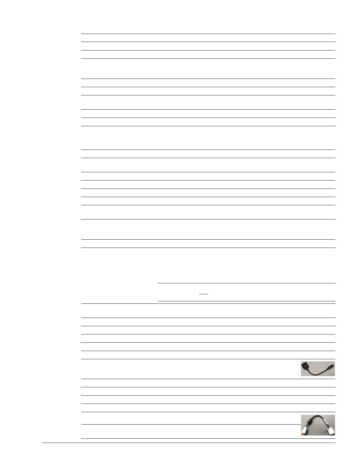
33 DVI Digital Video Output Connected to 34 with a splitter cable.
34 DVI Digital Video Output
Connected to 33 with a splitter cable, providing video out signal for
items 35, 37 and 36.