104
• Select Column
The checkboxes () in this column are used to select digital channels for simultaneous
modification using the Edit Assistance bar.
o All :
Check this box (All ) to select all the digital input channels to be modified simultaneously
using the Edit Assistance bar.
• Event#
This column displays the digital channel number for each physical input.
• Description
This column displays the alpha-numeric description entered for each digital input. The description
is limited to 64 characters.
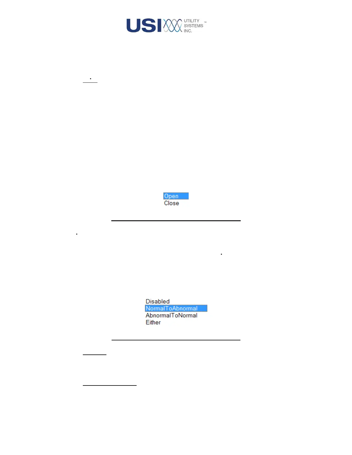
• Normal State
This column provides the drop-down menu used to assign the normal state for the contact being
monitored.
Figure 3-26 Normal State Drop-down Menu
• DFR
This checkbox is used to enable () the selected digital channel as a DFR input. This configures
the input to be recorded into DFR data files. Uncheck this box ( ) to disable the feature.
• DFR Trigger
This column is active when the DFR feature is enabled for the selected input. It provides the drop-
down menu to select a trigger mode for the digital input.
Figure 3-27 DFR Trigger Drop-down Menu
o Disabled:
This selection inhibits the DFR trigger function. It is selected when the measurement is
being exported only to Continuous data or output in the PMU data stream.
o Normal To Abnormal:
This selection enables the DFR trigger function to operate on a normal-to-abnormal
transition. The normal and abnormal conditions are defined by the limits assigned in the
Trigger If Over and Trigger If Under columns.
 Loading...