3
1.1 Model 9000 Module
This section describes the architecture of the M9000 module. This module performs real-time data
processing and communicates with the Station-Master computer. This is a required component of the DME
system. A Model 9000 DME system can have multiple M9000 modules.
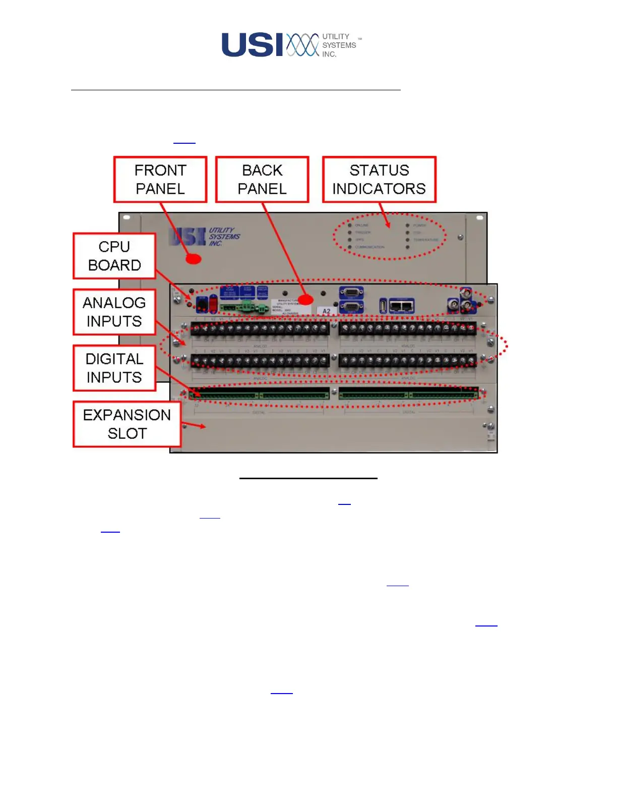
Figure 1-2 M9000 Module
The Model 9000 modules are typically housed in a standard 5U (8.75inH x 13.25inD x 19inW) rack mount
chassis. This unit contains a CPU board, a Backplane board, Analog and Digital Input boards, and a Front
Panel LED board.
The CPU board acts as the central processing unit for this module. This board is connected to the analog
and digital input boards through the Backplane board, and to the Front Panel LED board via ribbon cable.
For complete details on this board including specifications, see Section 1.1.1.
The Backplane board is used to attach the Analog and Digital Input boards to the CPU board for the
transfer of data, control signals, and power. For complete details on this board, see Section 1.1.3.
The Analog Input boards contain input voltage dividers, current shunts, surge protection, input-to-input
isolation, and input-to-ground isolation. This board also contains precision instrumentation amplifiers,
analog-to-digital converters, and a DC calibration reference for each analog input. For complete details on
this board and its specifications, see Section 1.1.4.


 To Next Page