15
1.1.3 Analog/Digital Backplane Board
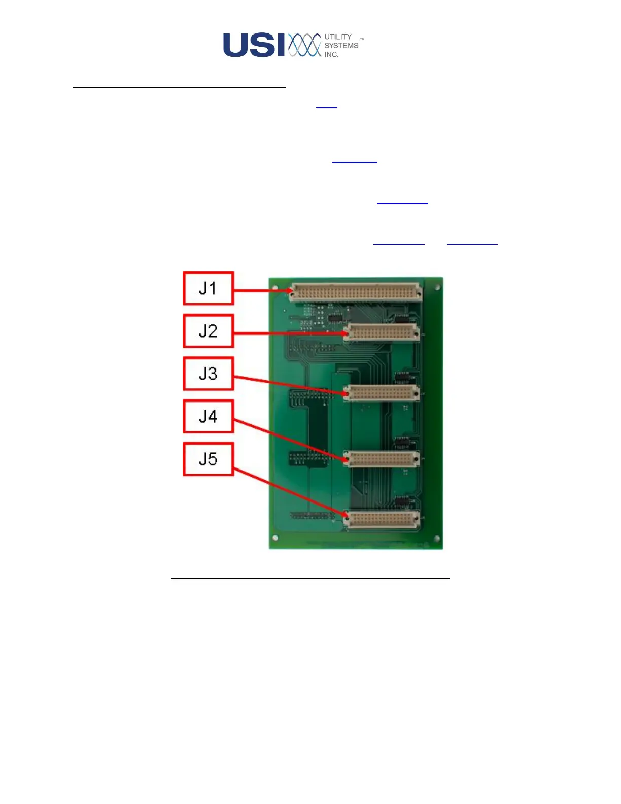
This board interfaces the input control signals from the CPU board and the digitized output signals from the
analog and digital input boards to the CPU board.
• J1
This connector attaches to J12 of the CPU board (Figure 1-4).
• J2 – J5
These connectors attach to CN1 of the analog input boards (Figure 1-11).
• J6 – J9
These connectors attach to CN3 of the digital input boards (Figure 1-13 and Figure 1-14) via 20-pin
ribbon cables.
Figure 1-9 Analog/Digital Adapter Board – Back Side

 Loading...