20
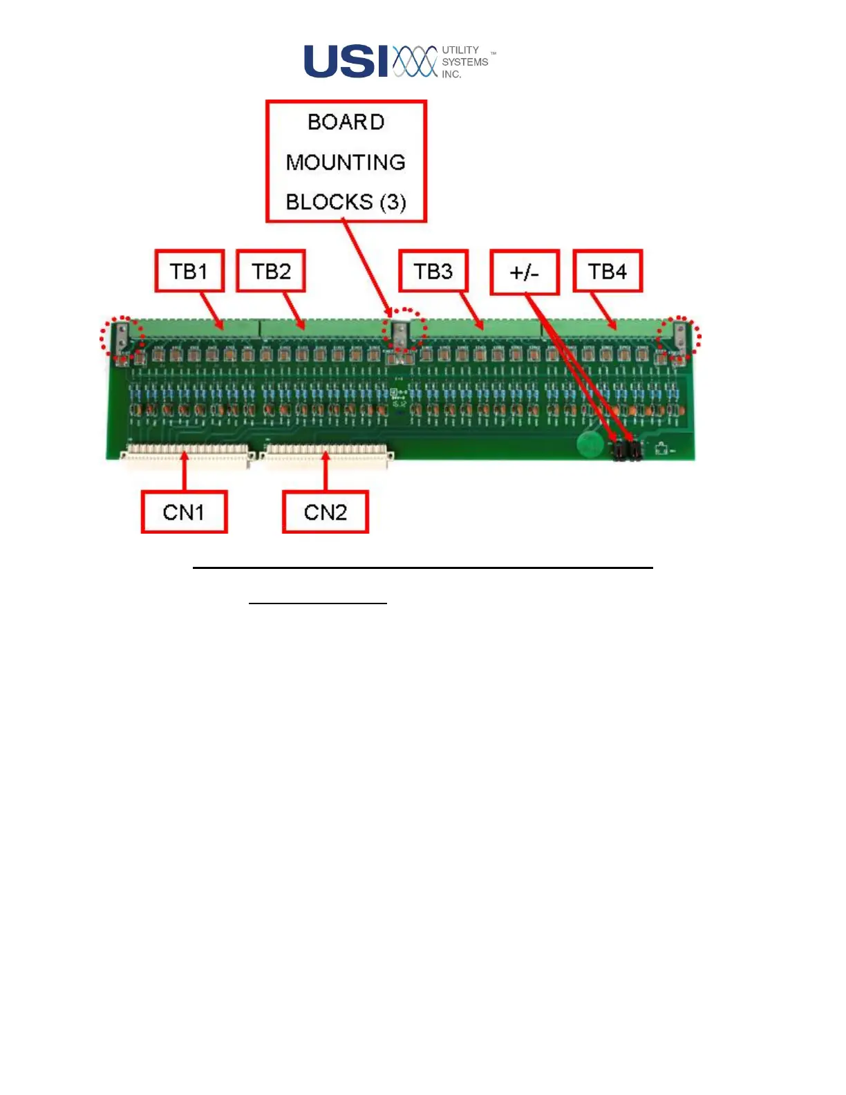
Figure 1-12 High-Voltage Digital Board (Single Board Assembly)
o Connector Description:
These connector functions are described below:
▪ CN1 and CN2
These connect the surge protected and reduced level signals to the Low-
Voltage Digital board.
▪ CN3 and CN4
These connectors supply field contact source voltage to the assembly via
rear panel terminal block. They are parallel connected to allow daisy-chain
connections to other High-Voltage Digital board assemblies within the
chassis. This connection is required for internally commoned and
internally wetted configurations only; it is not used for isolated
configurations.
▪ EGL1
This connector is unused.
▪ TB1
This terminal block accepts input numbers one through eight.