10
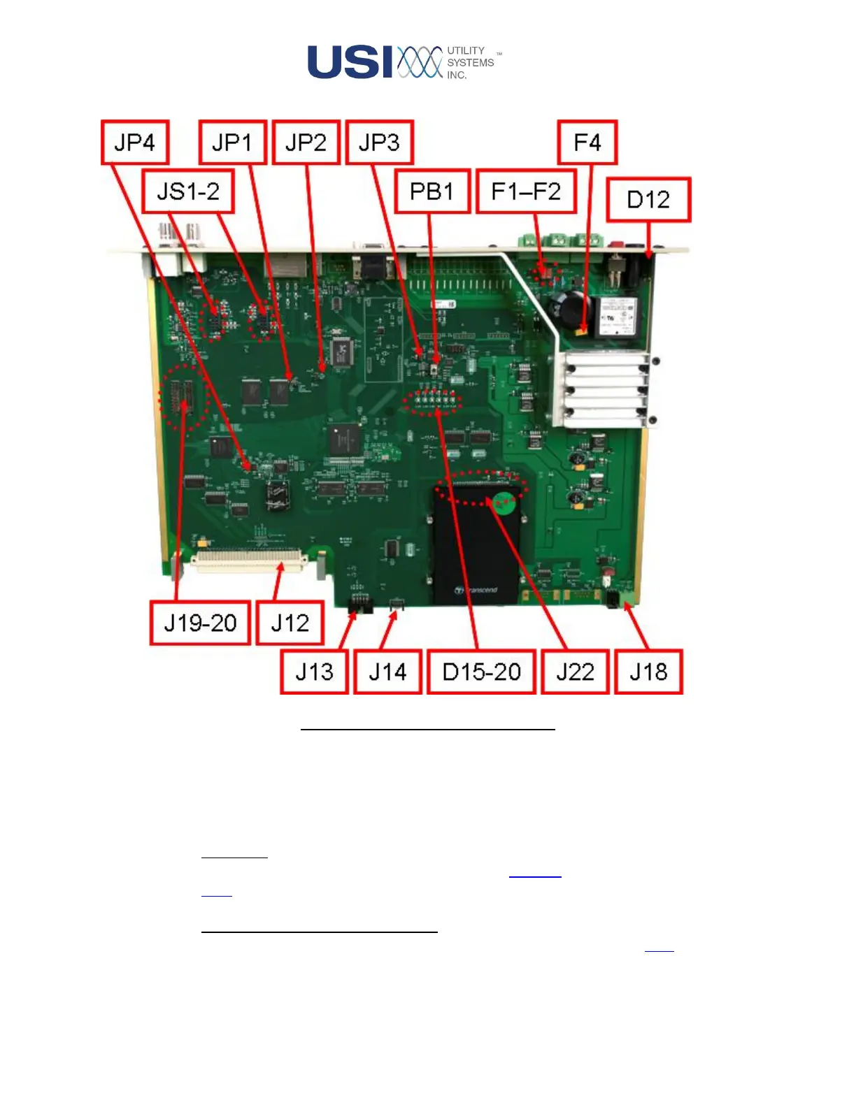
Figure 1-4 CPU 9000 Circuit Board
• Connector Descriptions:
These connectors are described below:
o JS1 – JS2:
These connectors are used to install the fiberoptic Ethernet daughter boards (see Section
1.1.2).
o J12 – Analog / Digital Backplane Input:
This connection is where the digitized analog and digital inputs enter the CPU board to be
processed. Through this connection, the CPU board also detects what boards are
connected to the Analog / Digital Adapter board and alarms when it disagrees with the