85
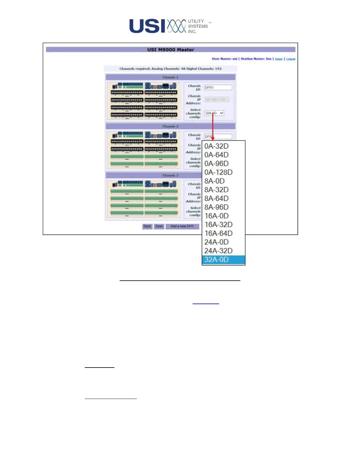
Figure 3-11 New Configuration Preview
A basic configuration for the DME system is automatically initiated based on the analog and digital
inputs entered on the New Station Details screen (Figure 3-1). The chassis diagrams displayed
show how the analog and digital inputs were distributed among the chassis. The example above
displays a 48 analog channels and 192 digital channels DME system.
The M9000 DME system has a distributed architecture; its chassis may be physically located in
several locations. To accommodate this type of installation, chassis configurations may need to be
modified and additional chassis added using the following controls:
o Chassis ID:
This field displays the name assigned to each chassis. The default names are: DFR1 for
chassis one, DFR 2 for chassis two, etc.
o Chassis IP Address:
This field displays the IP address assigned to this chassis on the DME network.