16
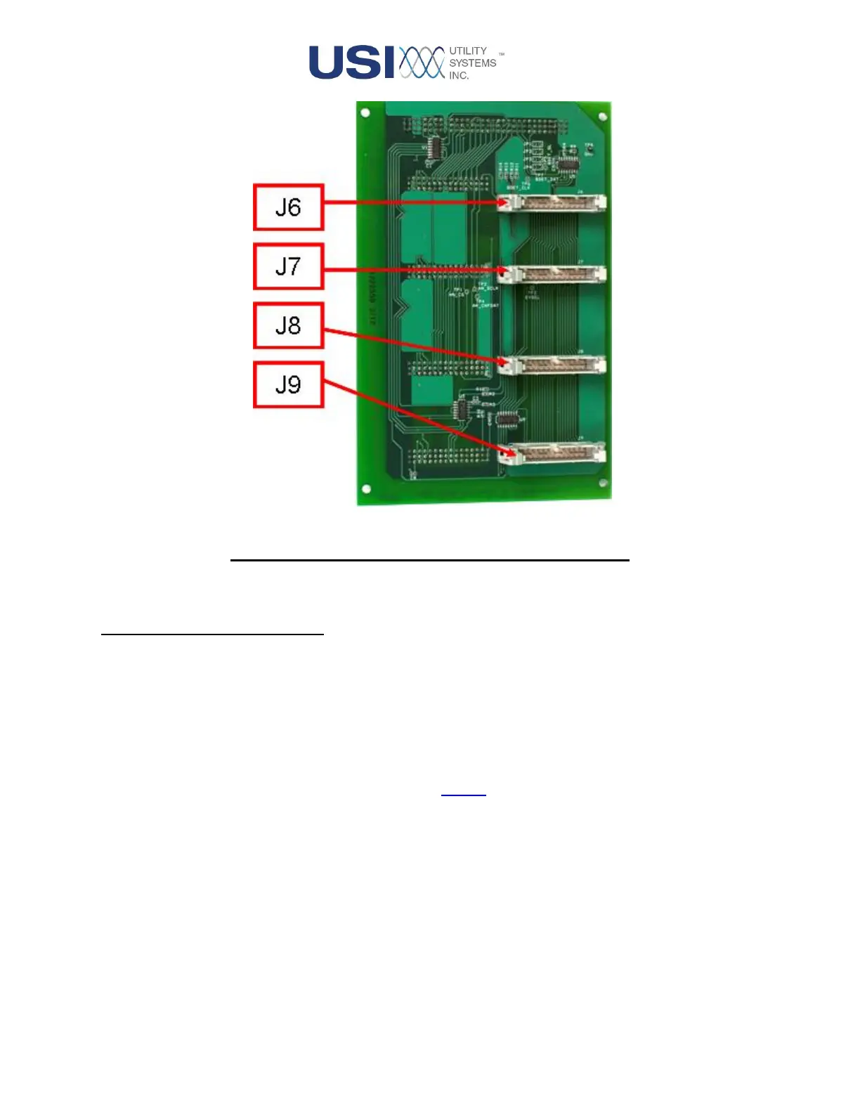
Figure 1-10 Analog/Digital Adapter Board – Front Side
1.1.4 Analog Input Circuitry
The analog input circuitry is used to measure and digitize signals on the analog input channels. It consists
of input voltage dividers, current shunts, surge protection devices, precision instrumentation amplifiers, low-
pass anti-aliasing filters, analog-to-digital converters, and a DC calibration reference for each analog input.
The analog assembly has eight inputs which accept AC or DC voltage or current signals. Each input
provides input-to-input isolation and input-to-ground isolation.
The board layout is arranged such that each input is in a self-contained section of the board for channel-to-
channel isolation. Each channel has a 5200VDC digital isolator for protection between the field inputs and
the equipment.
Two assemblies of this low pass filter board are available, each with a specific anti-aliasing cutoff
frequency:
• 4.8kHz Low Pass Filter (USI Assembly #18724857)
This is the default version which has a 4-pole Butterworth filter with 4.8kHz cut-off frequency.
• 10kHz Low Pass Filter (USI Assembly #18725598)
This is an optional version which has a 4-pole Butterworth filter with 10khz cut-off frequency.