36
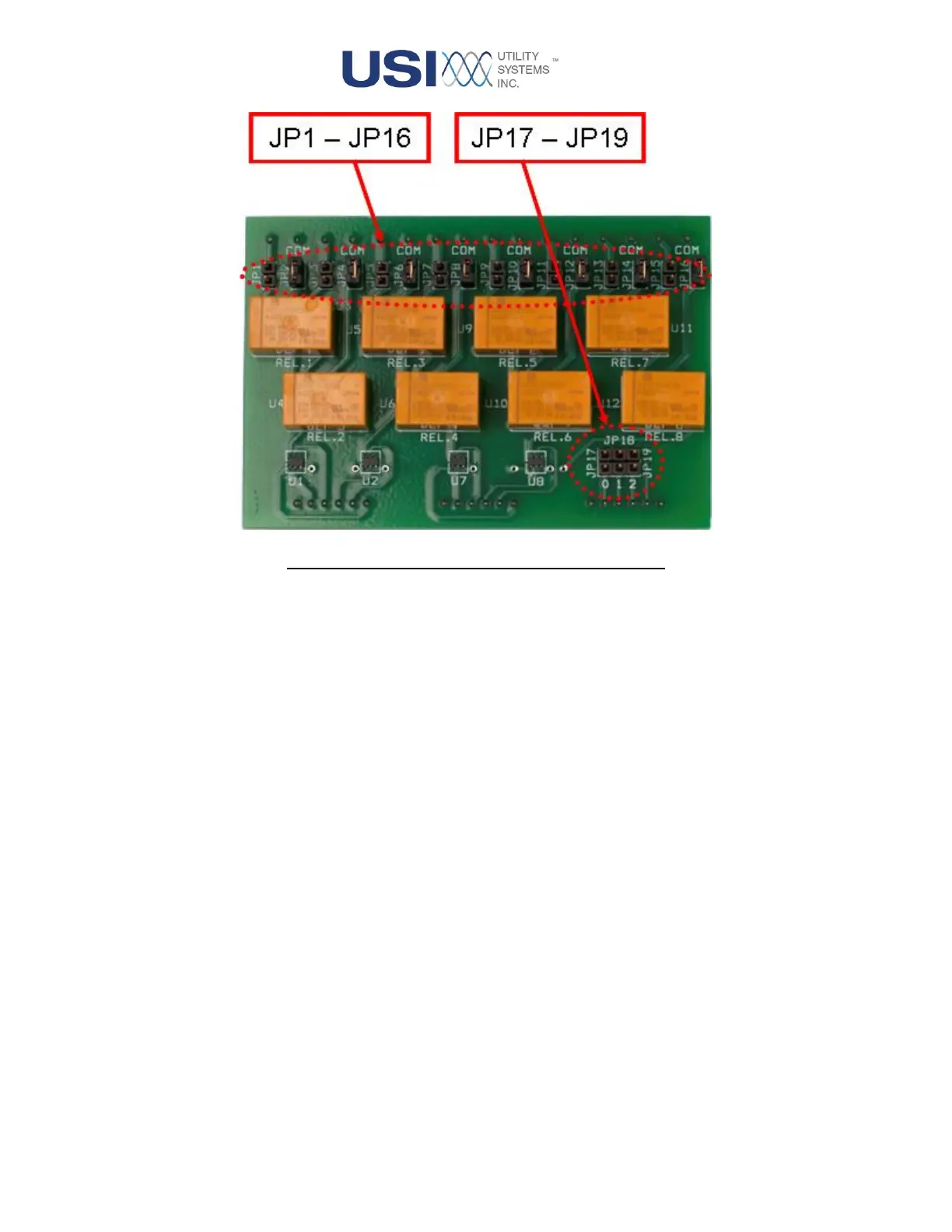
Figure 1-20 Alarm Output Board - Front View)
• JP1
This jumper programs the output of relay one which is the ON LINE alarm. Jumper these pins to
configure this relay to be normally open (open on alarm).
• JP2
This jumper programs the output of relay one which is the ON LINE alarm. Jumper these pins to
configure this relay to be normally closed (close on alarm).
• JP3
This jumper programs the output of relay two which is the TRIGGER alarm. Jumper these pins to
configure this relay to be normally open (open on alarm).
• JP4
This jumper programs the output of relay two which is the TRIGGER alarm. Jumper these pins to
configure this relay to be normally closed (close on alarm).
• JP5
This jumper programs the output of relay three which is the CLOCK SYNC alarm. Jumper these
pins to configure this relay to be normally open (open on alarm).
• JP6
This jumper programs the output of relay three which is the CLOCK SYNC alarm. Jumper these
pins to configure this relay to be normally closed (close on alarm).