7
The rear panel of this module has the following features:
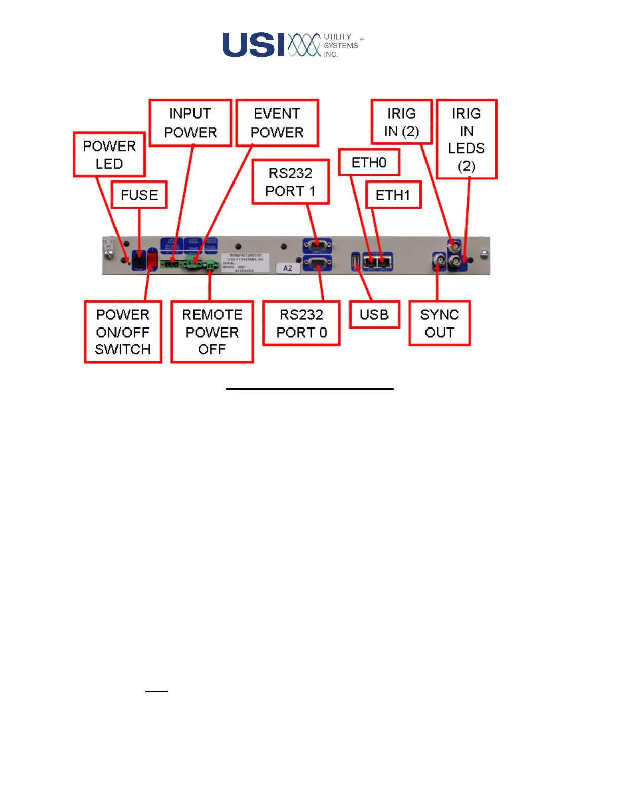
Figure 1-3 CPU 9000 Rear View
• Power Indicator
This green LED indicates that the power switch is in the ON position and the fuse is good.
• Fuse
This fuse protects the board from excessive input current.
• On / Off (1 / 0) Switch
This switch is used to control power for this module.
• Input Power
This connection is used to supply power to the module and is a required input. It accepts voltage
from the station battery and provides isolation and surge protection. The standard input
configuration is 125VDC or 120VAC. The input can also be factory configured to accept 250V or
48V DC input voltage.
• Event Power
This optional connection is relevant only when the DAU chassis contains a Digital Input module. It
serves two functions. One function is to monitor the presence of external Field Contact Voltage.
The other function is to apply Field Contact Voltage to be supplied from the Digital Input terminals.
Both input lines (+/-) pass through internal fuses and then routed to the digital input boards (see
Section 1.1.5).
 Loading...