11
M9000 configuration. The digitized signals are passed from the analog and digital input
boards to the CPU board via the Analog/Digital Backplane board (Section 1.1.3). Power
supply voltage is also supplied through this connector to power the analog and digital input
boards.
o J13 – JTAG:
This connection is used by USI factory personnel for initial startup of the CPU board. This
connection is not used in the field.
o J14 – LED Display Port:
This connection is used to communicate to the Front Panel LED board. Power supply
voltage is also supplied through this connector to power the LED display board.
o J18 – Event Power:
This connection is used to supply field contact voltage to the digital input boards.
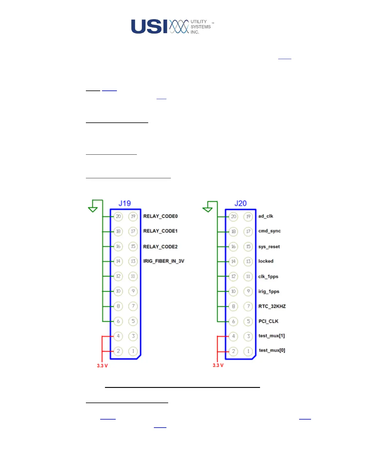
o J19 and J20 – TEST HEADERS:
These headers are used for bench testing.
Figure 1-5 Test Headers - CPU 9000 Circuit Board
o J22 – Storage Drive Connector:
This connection is used to install non-volatile storage on the CPU board. The interface is
2.5in PATA format. This connection supports the installation of a solid state drive (SSD) or
a rotating hard disk drive (HDD) and is used to store the M9000 module software. This