27
1.2 Station-Master Power Supply/Alarm Module
This section describes the architecture of the Station-Master Power Supply/Alarm module. This module
supplies power supply voltage to the Station-Master Computer and is a required component of the DME
system.
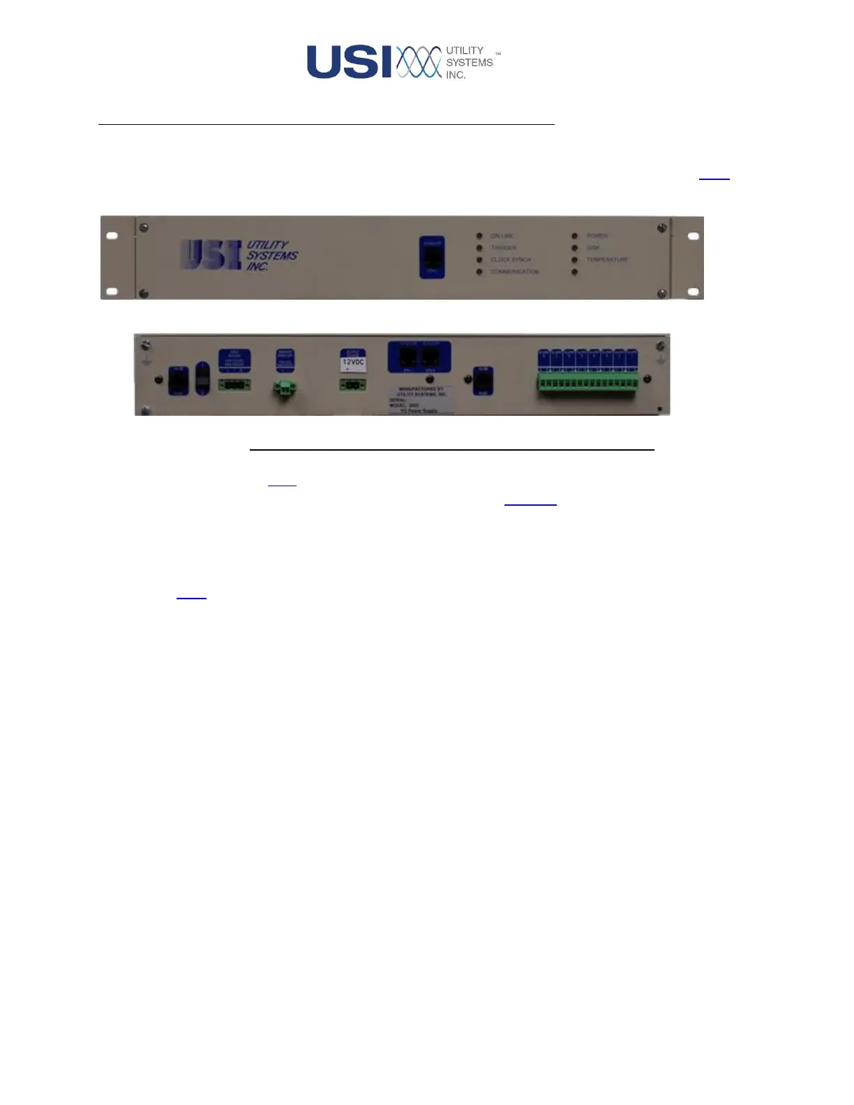
Figure 1-17 Computer Power Supply and Alarm Module
This module is housed in a 1.5U (2.625inH x 13.25inD x 19inW) rack mount chassis. This unit contains a
power supply board, an Interface board, a Relay Output board, an Ethernet switch, and a Front Panel LED
board.
This power supply unit can be factory configured to accept 250V, 125V, or 48V DC input voltage. The
standard / default input configuration is 125VDC or 120VAC input. For details on the power supply board
see Section 1.2.1.
The module is fanless by design and employs a robust heat sink assembly to cool the main DC-to-DC
converter by conducting heat to the chassis base plate.
This module contains a watch-dog circuit to monitor the health of the Station-Master computer. This circuit
will cycle the output power supply in the event of a Station-Master failure.
This module contains eight alarm relay outputs to provide DME system status to an alarm annunciator or
SCADA.
The rear panel of this module has the following features:
• 8A SB Fuse
This fuse protects the board from excessive input current.
• On / Off (1 / 0) Switch
This switch is used to control power for this module.
• Input Power
This connection is used to supply power to the module and is a required input. It accepts voltage
from the station battery and provides isolation and surge protection. The standard input
 Loading...