17
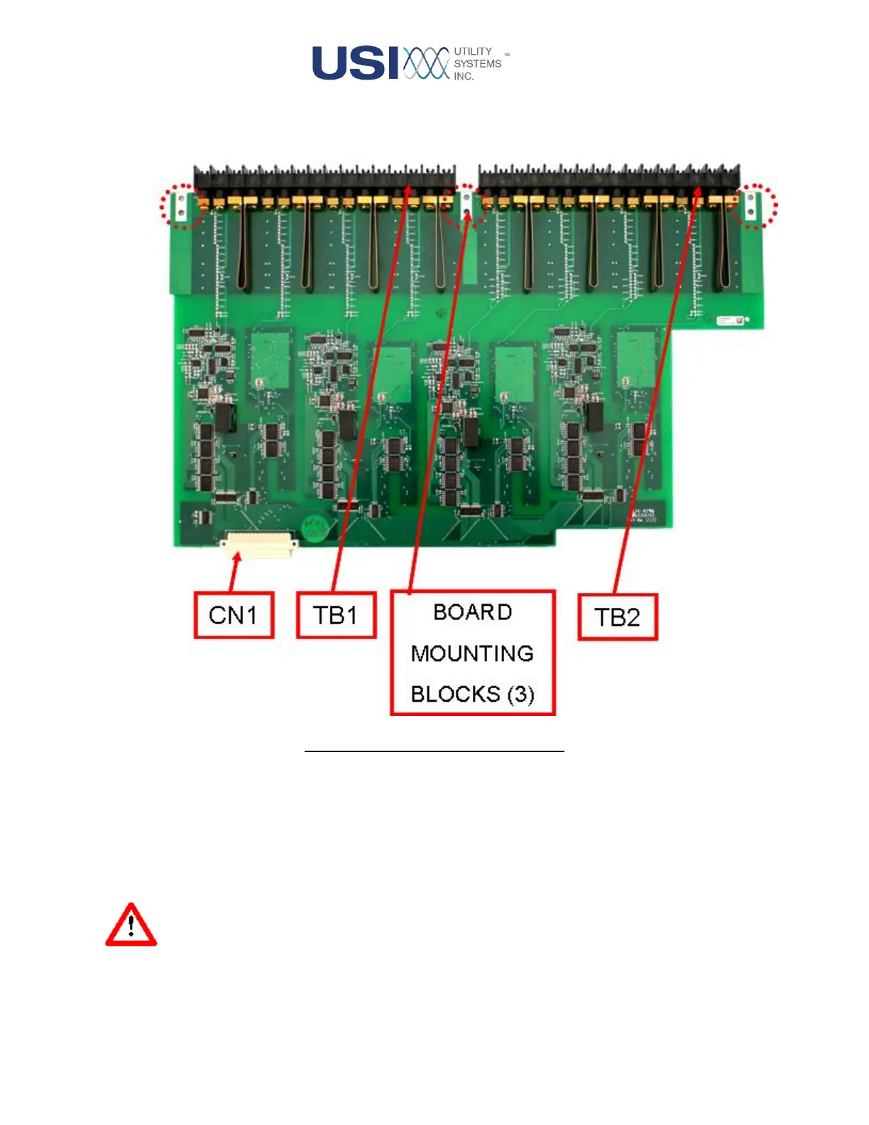
The assembly has two terminal blocks labeled TB1 and TB2, three earth ground connection blocks, and
one connector labeled CN1.
Figure 1-11 Analog Input Assembly
The terminal blocks protrude through the rear panel of the M9000 module and connect directly to the field
CT and PT circuits.
The board mounting blocks are used to attach the board to the chassis rear panel and are also utilized as
the electrical connection to ground the high-voltage surge suppression capacitors (See Warning
immediately below).
Warning: Equipment damage will occur if joints are not mechanically tight. Surge capacitors
must be grounded through mechanical joints between the circuit board mounting
blocks and the chassis rear panel.