38
• JP19
This jumper is not used.
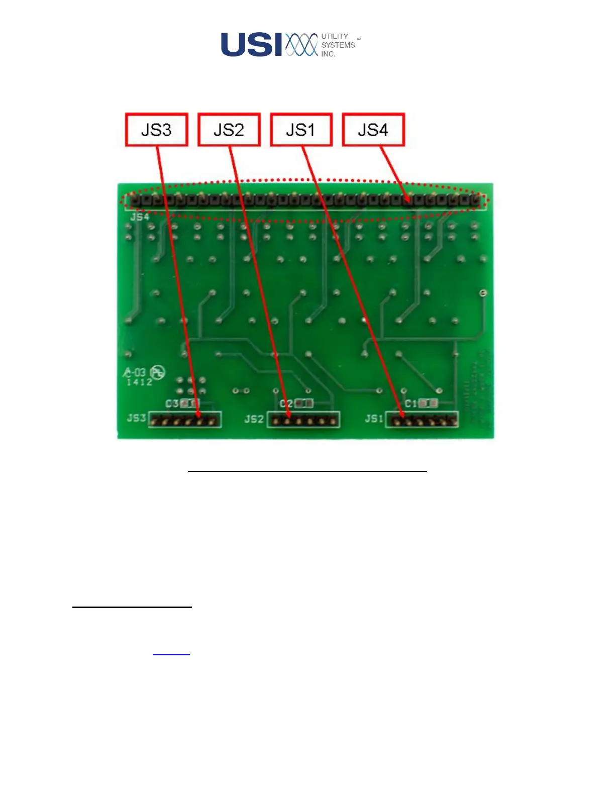
Figure 1-21 Alarm Output Board – Back View
• JS1 – JS3
These connections are the input connections and are also used to attach the Alarm Output board
to JS1 – JS3 on the Interface board.
• JS4
These connections are the output connections and are also used to attach the Alarm Output board
to JS1 – JS3 on the Interface board.
1.2.4 Ethernet Switch
This Ethernet switch is used to provide connections for ETH0 – ETH2 on the Station-Master Power
Supply module and to connect the Interface board to the local DME system network. This is an un-
managed Ethernet switch.