22
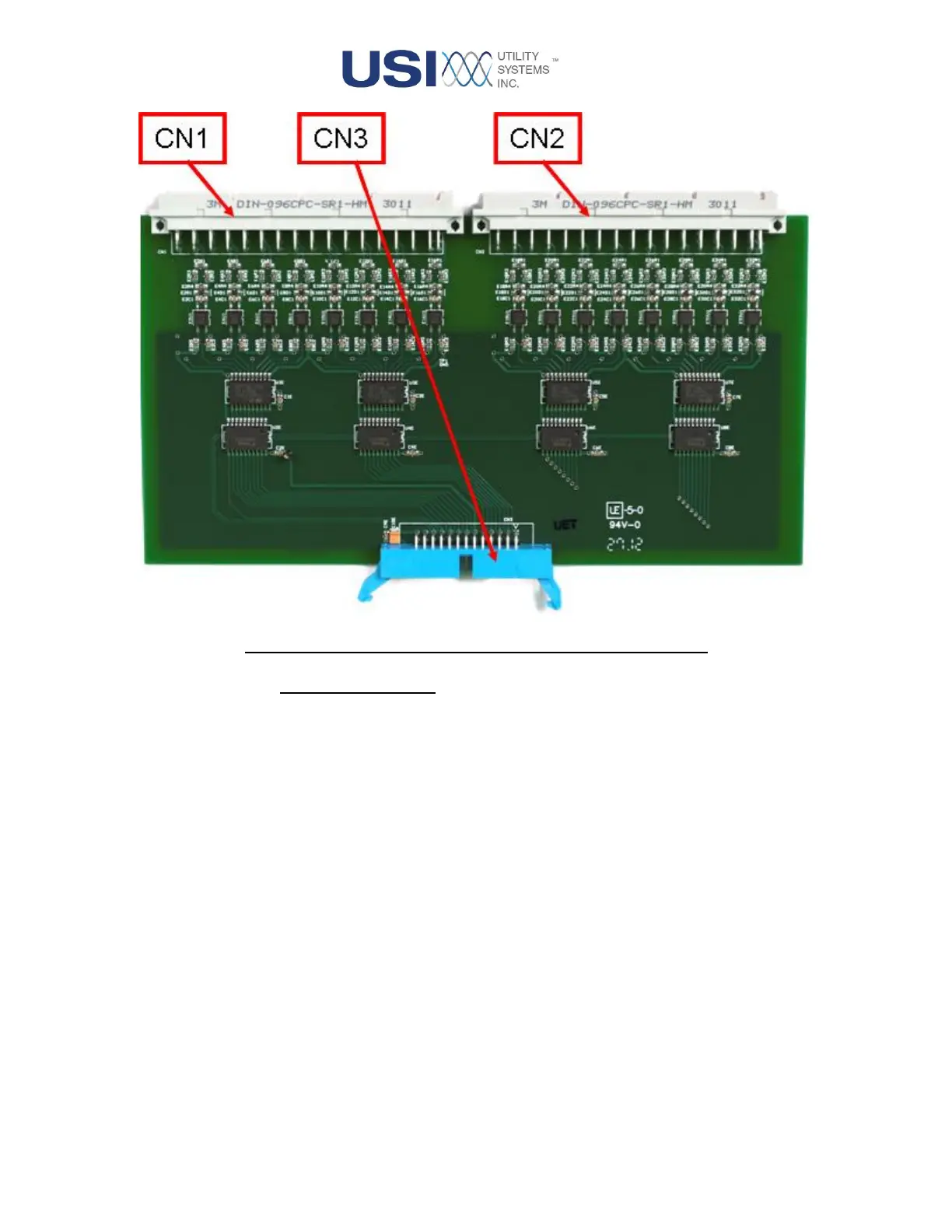
Figure 1-13 Low-Voltage Digital Board (First Generation)
o Connector Description:
These connector functions are described below:
▪ CN1 and CN2
These connect the board inputs to the High Voltage Digital board.
▪ CN3
This connects the sample clock signals from the CPU board and connects
the digitized data output to the CPU board.
• DIGITAL BOARD (SECOND GENERATION)
This generation is used in new construction and is backward compatible. This board combines the
voltage divider and surge suppression functions of the High-Voltage and optical isolation function
of the Low-Voltage Digital boards into a single board assembly. The standard input range for this
generation is 40VDC to 250VDC.