Maintenance
1132−2/A1
Winterthur Gas & Diesel Ltd.
9/ 14
4.3 Bearing Shell No. 1 −
Removal
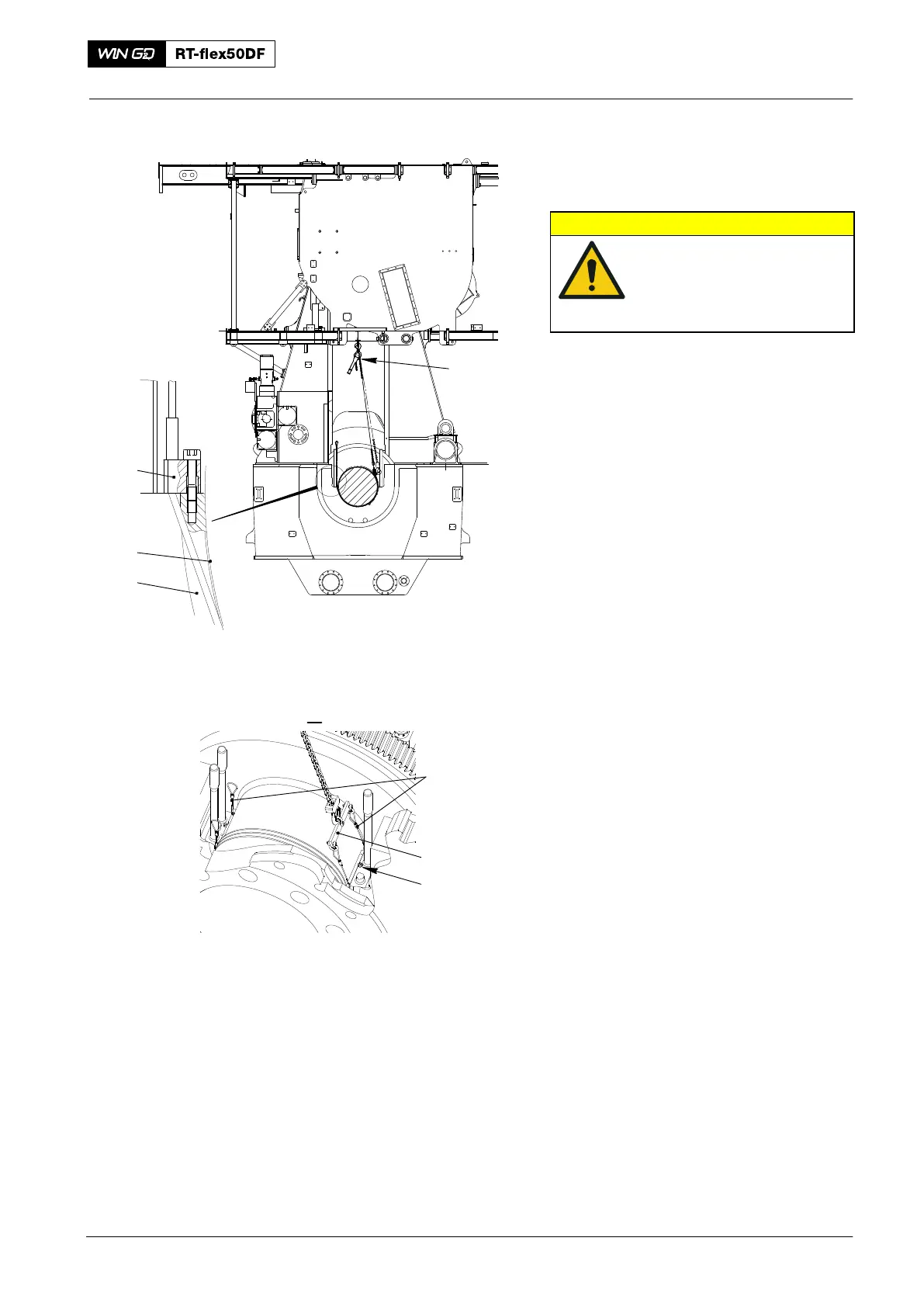
CAUTION
Damage Hazard: Do not
remove two adjacent main
bearing shells at the same
time. Damage to the engine
can occur.
Note: The applicable main bearing cover
is removed.
1) Make sure that the crankshaft is lifted
to 0.2 mm. Refer to paragraph 4.1 and
paragraph 4.2.
2) Attach the manual ratchet (H1, Fig. 11)
to the platform.
3) Remove the Allen screws (1) from the
bearing girder.
4) Attach the device (94119B) to the
manual ratchet (H1)
.
5) Attach the turning-out device (94118A)
to the main bearing shell (3).
6) Put the wire ropes (3) along the outer
edges of the bearing shell to the other
side and attach them to the device
(94119B) as shown.
Main Bearing − Removal and Installation
2016
94118A
H1
94119B
1
018.604/09
94118A
I
2
3
Fig. 11