Maintenance1132−2/A1
Winterthur Gas & Diesel Ltd.
10/ 14
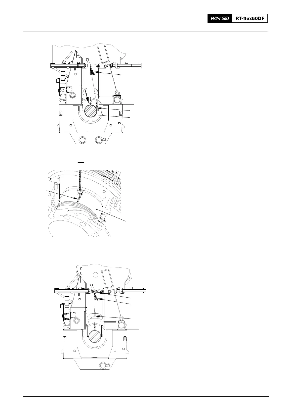
7) Operate the manual ratchet (H1,
Fig. 12) to turn the bearing shell (1) to
the position as shown.
Note: If the bearing shell (1) does not
move, the device (94119B) must be
attached to the other side of the
turning-out device (94118A). The
bearing shell must be moved back
to its initial condition and the
removal procedure done again.
8) Remove the turning-out
device (94118A).
9) Attach the tool (94116A) to the bearing
shell (1).
10) Attach the manual ratchet (H2) to the
trolley (94116 Fig. 13) and the tool
(94116A) as shown.
Note: During step 11), make sure that
each end of the bearing shell (1)
does not touch the bearing girder.
11) Operate the manual ratchet (H1) to lift
the bearing shell (1). At the same time,
operate the manual ratchet (H2) to
keep tension on the chain.
12) Carefully remove the manual
ratchet (H1).
13) Move the trolley (94116A), manual
ratchet (H2) and the bearing shell until
there is sufficient clearance to lower the
bearing shell.
14) Carefully lower the bearing shell on to a
wooden underlay.
Main Bearing − Removal and Installation
2016
Fig. 12
94116A
1
H1
I
018.601/09
94116A
I
1
Fig. 13
94116
H2
94116A