Maintenance
1132−2/A1
Winterthur Gas & Diesel Ltd.
11/ 14
4.4 Bearing Shell No. 2 to No. 8
− Removal
WARNING
Injury Hazard: Before you
operate the turning gear,
make sure that no
personnel are near the
flywheel or in the engine.
CAUTION
Damage Hazard: Do not
remove two adjacent main
bearing shells at the same
time. Damage to the engine
can occur.
Note: The bearing cover and the top
main bearing shell are removed.
1) Remove the work platform (94143).
2) Unlock the turning gear.
3) Operate the turning gear to turn the
applicable crank to the exhaust side
approximately 90_ after TDC.
4) Lock the turning gear to prevent
movement.
5) Attach the work platform (94143).
6) Lift the crankshaft, refer to paragraph
4.1 and 4.2.
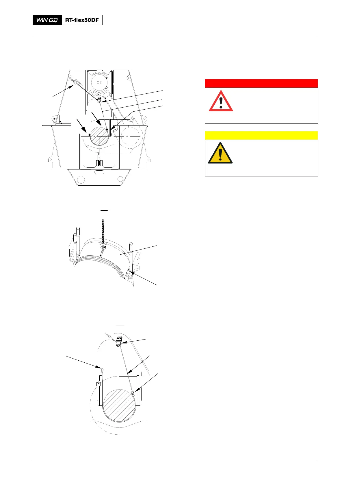
7) Remove the two Allen screws (2) from
the bearing shell.
8) Attach the device (94117, Fig. 14) to
the column with its dowel pin and
spring clip.
9) Attach the turning-out device (94118A)
to the bearing shell.
10) Put the ropes of the turning-out device
(94118A) along the outer edges of the
of the bearing shell to the other side
and attach them to the
device (94119B).
11) Attach the manual ratchet (H1) to the
column and the wire rope (94120A).
Main Bearing − Removal and Installation
2016
Fig. 14
II
94118A
H1
94120A
94117
94119B
94120A
94119B
94120A
018.601/09
I
1
II
I
2