Maintenance
2751−1/A1
Winterthur Gas & Diesel Ltd.
3/ 8
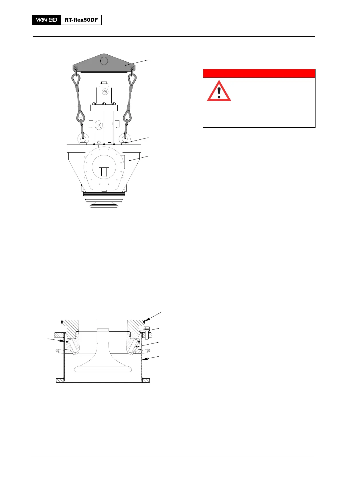
2.2 Exhaust Valve − Removal
WARNING
Injury Hazard: The weight
of the suspension tool
(94265) is 33.4 kg. Use
applicable equipment and
personnel to move and
install the suspension
device.
1) Attach the two special eye nuts
(94265A, Fig. 3) to the exhaust
valve (1).
2) Attach the engine room crane to the
suspension tool (94265).
3) Attach the suspension tool (94265) to
the special eye nuts (94265A).
4) Operate the engine room crane to
remove the exhaust valve (1) from the
cylinder cover.
5) Remove and discard the O-rings (1 and
4, Fig. 4).
6) Attach the valve protector (94262) to
the valve seat (3).
7) Tighten the three screws (2).
8) Move the exhaust valve to an
applicable area.
9) If necessary, lower the exhaust valve
on to a wooden underlay.
2.3 Elastic Studs − Examine
1) Examine the elastic studs for damage.
If it is necessary to replace the elastic
studs, do the procedure given in
paragraph 5 before you install the
exhaust valve.
2016
Removal and Installation of Exhaust Valve, Replacement of Elastic Studs
94265
Note: Some parts can look different
94265A
Fig. 3
94262
4
WCH03194
Fig. 4
1
2
3
1