Maintenance2751−1/A1
Winterthur Gas & Diesel Ltd.
6/ 8
4. Completion
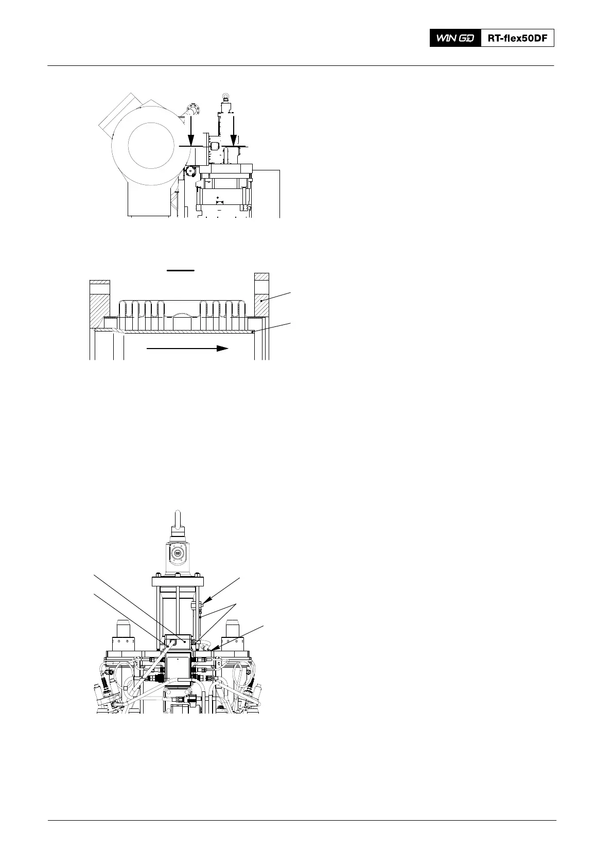
1) Clean the sealing faces on the
expansion piece (1, Fig. 10) and the
related sealing faces on the valve cage
and exhaust manifold.
2) Apply a thin layer of a heat-resistant
lubricant to the sealing faces and
related screws.
3) Use the applicable tools and equipment
to put the expansion piece (1) in
position. Make sure that the direction of
flow is correct, i.e. the protection
pipe (2) is in the correct position
(nearest to the valve cage).
4) Install all pipes that you removed in
paragraph 1.
5) Install the hydraulic pipe, refer to
8460−1.
6) Connect the electrical connections (2,
Fig. 11) to the terminal box (4) and the
valve stroke sensor (1).
7) Attach the electrical cable of the valve
stroke sensor (1) to the valve cage and
the holder (3).
8) Open the air inlet to the air spring at the
control air supply.
9) Fill the cylinder cooling water to the
applicable cylinder.
2018−02
Removal and Installation of Exhaust Valve, Replacement of Elastic Studs
WCH03087
4
2
2
3
1
II
WCH03087
I - I
WCH03087
Direction of Flow
Fig. 10
1
2
Fig. 11
WCH03193