ENGINE
B2420, WSM
1-S41
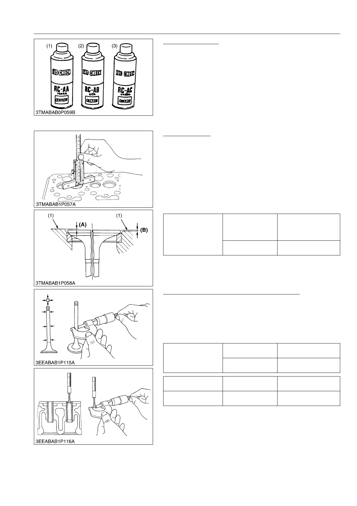
Cylinder Head Flaw
1. Prepare an air spray red check (Code No. 07909-31371).
2. Clean the surface of the cylinder head with detergent (2).
3. Spray the cylinder head surface with the red permeative liquid
(1). Leave it five to ten minutes after spraying.
4. Wash away the red permeative liquid on the cylinder head
surface with the detergent (2).
5. Spray the cylinder head surface with white developer (3).
6. If flawed, it can be identified as red marks.
9Y1210436ENS0062US0
Valve Recessing
1. Clean the cylinder head surface, valve face and valve seat.
2. Insert the valve into the valve guide.
3. Measure the valve recessing with a depth gauge.
4. If the measurement exceeds the allowable limit, replace the
valve.
5. If it still exceeds the allowable limit after replacing the valve,
correct the valve seat face of the cylinder head with a valve seat
cutter (Code No. 07909-33102) or valve seat grinder.
6. Then, correct the cylinder head surface with a surface grinder,
or replace the cylinder head0
9Y1210436ENS0063US0
Clearance between Valve Stem and Valve Guide
1. Remove carbon from the valve guide section.
2. Measure the valve stem O.D. with an outside micrometer.
3. Measure the valve guide I.D. with a small hole gauge, and
calculate the clearance.
4. If the clearance exceeds the allowable limit, replace the valves.
If it still exceeds the allowable limit, replace the valve guide.
9Y1210436ENS0064US0
(1) Red Permeative Liquid
(2) Detergent
(3) White Developer
Valve recessing
Factory specification
0.050 (protrusion) to
0.25 (recessing) mm
0.0020 (protrusion) to
0.0098 (recessing) in.
Allowable limit
0.40 (recessing) mm
0.016 (recessing) in.
(1) Cylinder Head Surface (A) Recessing
(B) Protrusion
Clearance between
valve stem and valve
guide
Factory specification
0.035 to 0.065 mm
0.0014 to 0.0025 in.
Allowable limit
0.10 mm
0.0039 in.
Valve stem O.D. Factory specification
6.960 to 6.975 mm
0.2741 to 0.2746 in.
Valve guide I.D. Factory specification
7.010 to 7.025 mm
0.2760 to 0.2765 in.