ELECTRICAL SYSTEM
B2420, WSM
9-S11
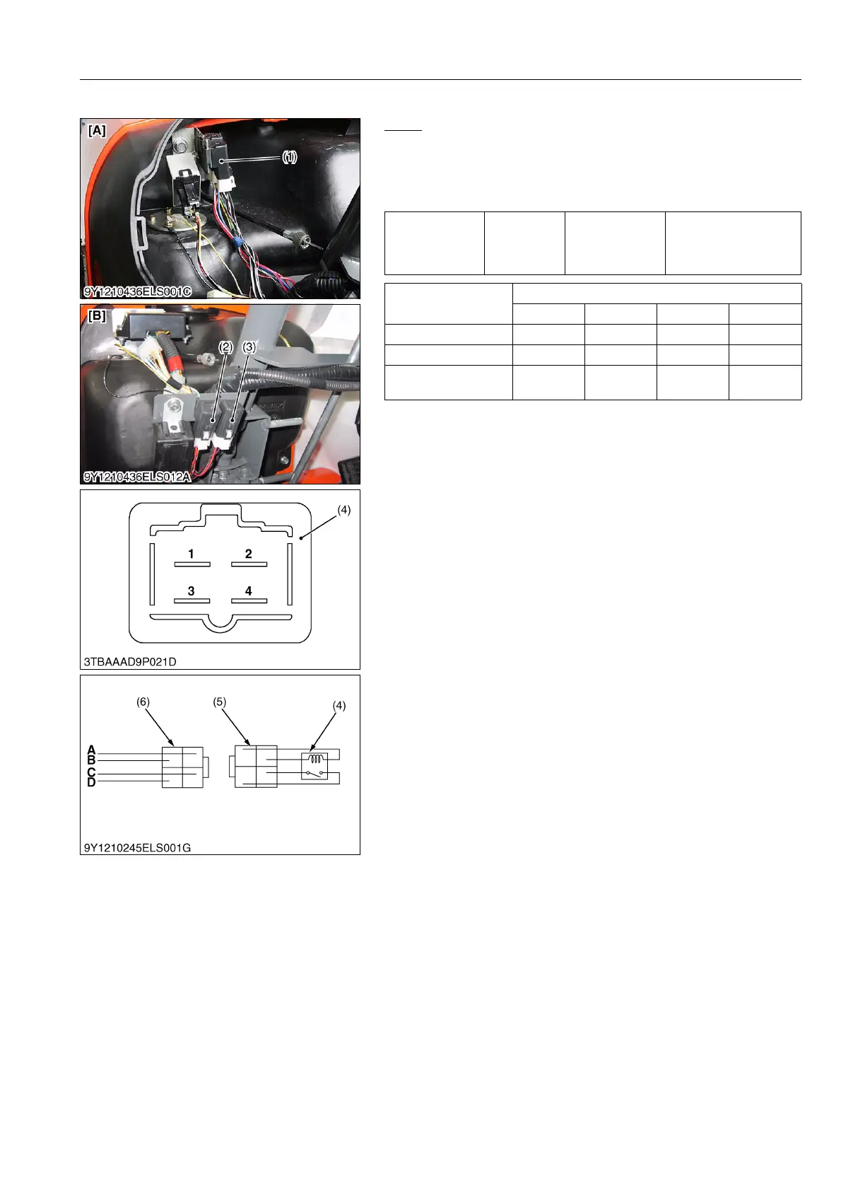
(3) Relay
Relay
1. Remove the panel board and starter relay (1).
2. Apply battery voltage across 2 terminal and 4 terminal, and
check for continuity across 1 terminal and 3 terminal.
3. If 0 Ω is not indicated, renew the starter relay (1).
9Y1210436ELS0077US0
Resistance
1 terminal –
3 terminal
Battery voltage is
applied across
2 terminal and
4 terminal
0 Ω
Connector of Wiring
Harness
Color of Wiring
1234
Starter Relay 2 B/W 2 B/W 0.5 B/R 0.5 B/W
Relay 0.5 W 0.5 W/R 0.5 W 0.5 W/R
Key Stop Solenoid
Relay
2 R/B 2 B/W 0.5 B/R 0.5 B
(1) Starter Relay
(2) Relay
(3) Key Stop Solenoid Relay
(4) Relay
(5) Connector (Wiring Harness)
(5) Connector (Relay)
1 to 4: Terminals
[A] Without OPC Model
[B] With OPC Model