HYDRAULIC SYSTEM
B2420, WSM
8-S6
(2) Relief Valve
Relief Valve Setting Pressure
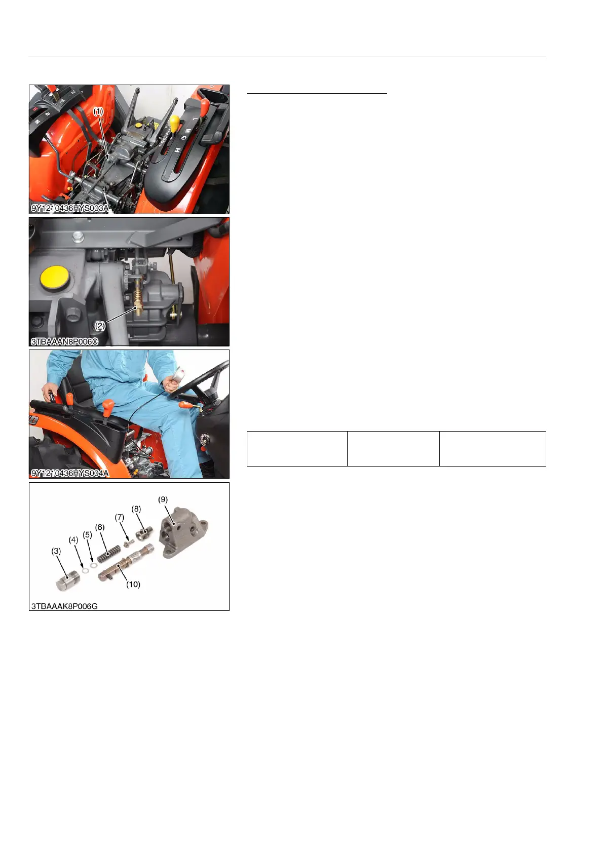
1. Remove the seat.
2. Remove the seat under cover.
3. Remove the plug (1) from the hydraulic cylinder.
4. Install the adaptor. Then connect the cable and the pressure
gauge to the adaptor 58.
5. Remove the feed back rod lock nut (2).
6. Start the engine and set the engine speed at approx. 2600 min
-1
(rpm).
7. Move the hydraulic control lever all way up to operate the relief
valve and measure the pressure.
8. If the pressure is not factory specifications, adjust the relief
valve setting pressure with the adjusting shims (5).
9. After checking the pressure, reinstall the feed back rod lock nut
and the plug (1).
Condition
• Engine speed
Approx. 2600 min
-1
(rpm)
• Oil temperature
50 °C (122 °F)
(Reference)
• Thickness of shims (5)
0.10 mm (0.0039 in.)
0.20 mm (0.0079 in.)
0.40 mm (0.016 in.)
• Pressure variation with 0.10 mm (0.0039 in.) difference of
adjusting shim thickness.
Approx. 264.8 kPa (2.7 kgf/cm
2
, 38 psi)
9Y1210436HYS0006US0
Relief valve setting
pressure
Factory specification
13.7 to 14.4 MPa
140 to 147 kgf/cm
2
1990 to 2090 psi
(1) Plug
(2) Lock Nut
(3) Plug
(4) Plain Washer
(5) Shim
(6) Spring
(7) Poppet
(8) Valve Seat
(9) Hydraulic Control Valve Body
(10) Spool