ENGINE
B2420, WSM
1-S40
[4] SERVICING
(1) Cylinder Head and Valves
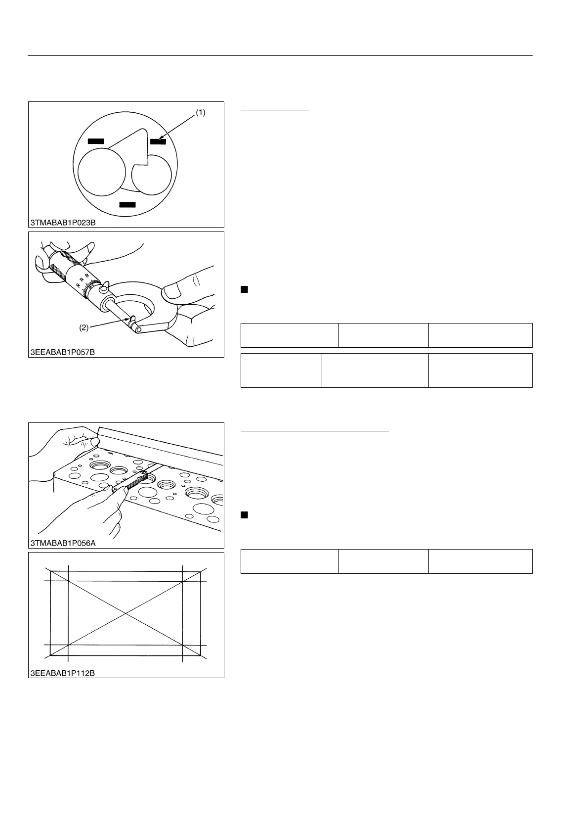
Top Clearance
1. Remove the cylinder head. (Do not attempt to remove the
cylinder head gasket.)
2. Move the piston up, and stick a strip of plastigage [1.5 mm dia.
(0.059 in. dia.), 5 to 7 mm long (0.197 to 0.276 in. long)] on the
piston head at three positions with grease so as to avoid the
intake and exhaust valves and the combustion chamber ports.
3. Lower the piston, and install the cylinder head and tighten the
cylinder head screws to the specified torque.
4. Turn the crankshaft until the piston exceeds its top dead center.
5. Remove the cylinder head, and measure the thickness of the
squeezed plastigages.
6. If the measurement is not within the factory specifications,
check the oil clearance between the crankpin and crankpin
bearing and between the piston pin and small end bushing.
• After checking the top clearance, be sure to assemble the
cylinder head with a new cylinder head gasket.
9Y1210436ENS0101US0
Cylinder Head Surface Flatness
1. Clean the cylinder head surface.
2. Place a straightedge on the cylinder head's four sides and two
diagonal as shown in the figure.
3. Measure the clearance with a feeler gauge.
4. If the measurement exceeds the allowable limit, correct it with a
surface grinder.
• Do not place the straightedge on the combustion chamber.
• Be sure to check the valve recessing after correcting.
9Y1210436ENS0061US0
Top clearance Factory specification
0.55 to 0.75 mm
0.022 to 0.029 in.
Tightening torque Cylinder head screw
64 to 68 N·m
6.5 to 7.0 kgf·m
47 to 50 lbf·ft
(1) Plastigage (2) Plastigage
Cylinder head surface
flatness
Allowable limit
0.05 mm
0.002 in.