ELECTRICAL SYSTEM
B2420, WSM
9-S16
(7) Key Stop Solenoid
Lead Terminal Voltage
1. Disconnect the connector of engine stop solenoid.
2. Turn the main switch "ON".
3. Measure the voltage with voltmeter across the terminal 1 and 2
(Red / Green and White) of the wiring harness side and the
chassis.
4. If the battery voltage (11 to 14 V) is not indicated, the fuse, the
main switch or wiring harness are faulty.
9Y1210436ELS0037US0
Key Stop Solenoid Test
1. Disconnect the lead from the engine stop solenoid after turning
the main switch off.
2. Connect jumper leads from the battery positive terminal to the
key stop solenoid terminal 1 (Red / Black) and 2 (White), then
from the battery negative terminal to the key stop solenoid body.
3. If the solenoid plunger is not attracted, the key stop solenoid is
faulty.
9Y1210436ELS0038US0
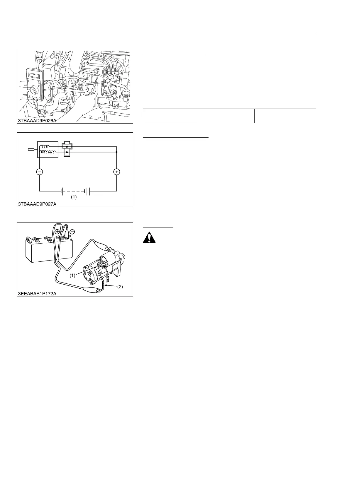
(8) Starter
Motor Test
• Secure the starter to prevent it from jumping up and down
while testing the motor.
1. Disconnect the battery negative cable from the battery.
2. Disconnect the battery positive cable and the leads form the
starter M terminal.
3. Remove the starter from the engine.
4. Disconnect the connecting lead (2) from the starter C terminal
(1).
5. Connect a jumper lead from the connecting lead (2) to the
battery positive terminal post.
6. Connect a jumper lead momentarily between the starter motor
housing and the battery negative terminal post.
7. If the motor does not run, check the motor.
9Y1210436ELS0039US0
Voltage
Ter mi na l 1 and 2 –
chassis
Approx. battery voltage
(1) Battery
(1) C Terminal (2) Connecting Lead