BRAKES
B2420, WSM
5-S9
[3] SERVICING
Clearance between Brake Pedal Shaft and Center Frame Bush
1. Measure the brake pedal shaft O.D. with an outside micrometer.
2. Measure the bush (3) I.D. with a cylinder gauge.
3. If the clearance exceeds the allowable limit, replace it.
9Y1210436BRS0008US0
Brake Cam Lever Movement
1. Move the brake cam lever by hand to check the movement.
2. If the movement is heavy, refine the brake cam with emery
paper.
9Y1210436BRS0009US0
Cam Plate Flatness and Bearing Holder Wear
1. Place a straightedge of 150 mm (5.91 in.) or more in length on
the contacting surface of the cam plate and the bearing holder.
2. Inspect the friction surface of the cam plate and the bearing
holder with the straightedge, and determine if a 0.30 mm
(0.012 in.) feeler gauge will fit on the part of wear.
3. If it will fit, resurface.
9Y1210436BRS0010US0
Height of Cam Plate and Ball
1. Measure the dimensions of the cam plate with the ball installed.
2. If the measurement is less than the allowable limit, replace the
cam plate and balls.
3. Inspect the ball holes of cam plate for uneven wear.
4. If the uneven wear is found, replace it.
9Y1210436BRS0011US0
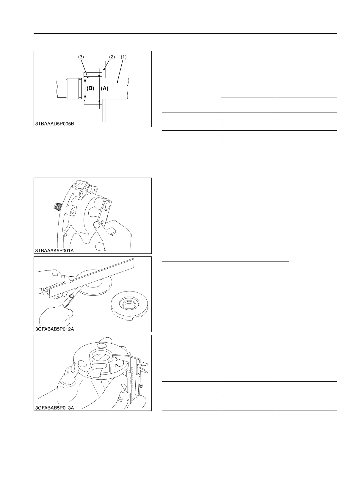
Clearance between
brake pedal shaft and
center frame bush
Factory specification
0 to 0.165 mm
0 to 0.00649 in.
Allowable limit
1.0 mm
0.039 in.
Brake pedal shaft O.D. Factory specification
24.916 to 25.030 mm
0.98095 to 0.98543 in.
Center frame bush I.D. Factory specification
25.030 to 25.081 mm
0.98544 to 0.98744 in.
(1) Brake Pedal Shaft
(2) Center Frame
(3) Bush
(A) Bush I.D.
(B) Brake Pedal Shaft O.D.
Height of cam plate and
ball
Factory specification
22.89 to 22.99 mm
0.9012 to 0.9051 in.
Allowable limit
22.40 mm
0.8819 in.