STEERING
B2420, WSM
7-M3
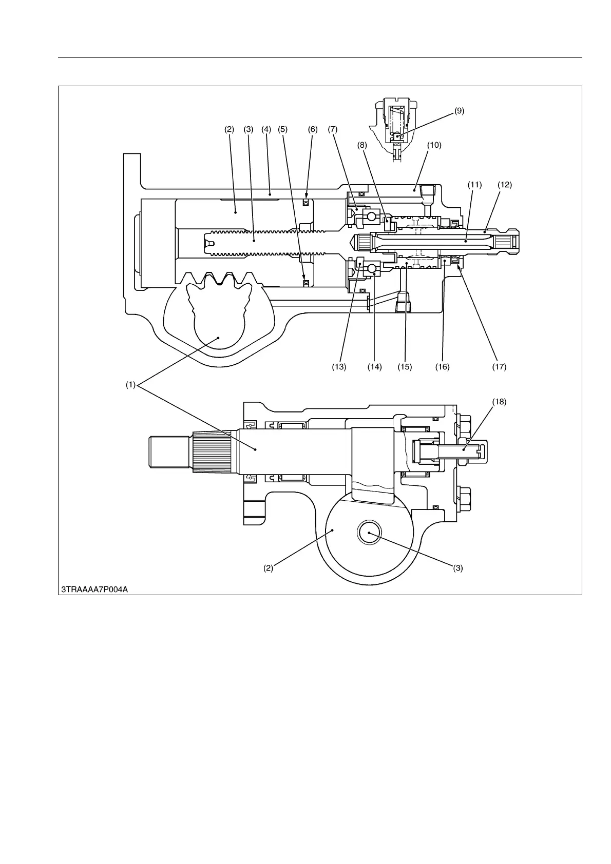
(2) Power Steering Body
The input shaft (stub shaft) (12) and the worm shaft (3), which can separate from each other, are jointed together
via a torsion bar (11). One end of the torsion bar is fixed by a pin with the stub shaft (12), where as the other end is
press fitted to the end of the worm shaft (3).
The control valve consists of a sleeve (15) and a spool (12). The sleeve is coupled by a pin to the worm shaft (3),
and the spool is provided on the stub shaft (12).
When a turning torque in either direction is given to the stub shaft (12), the counter force of the tires is produced
from the sector gear shaft (1) through the drag link, pitman arm and other parts. The torsion bar (11) then gets under
torsional force. In this way, the positional relation between the sleeve (15) and spool (12) changes, thereby switching
the direction of the oil flowing into the right and left cylinders.
9Y1210436STM0003US0
(1) Sector Gear Shaft
(2) Rack (Piston)
(3) Worm Shaft
(4) Gear Case
(5) O-ring
(6) Seal Ring
(7) Plug
(8) Pin
(9) Relief Valve
(10) Valve Housing
(11) Torsion Bar
(12) Stub Shaft (Spool)
(13) Staking Ring
(14) Ball Bearing
(15) Sleeve
(16) Bearing
(17) Oil Seal
(18) Adjusting Screw for Play