HYDRAULIC SYSTEM
B2420, WSM
8-S10
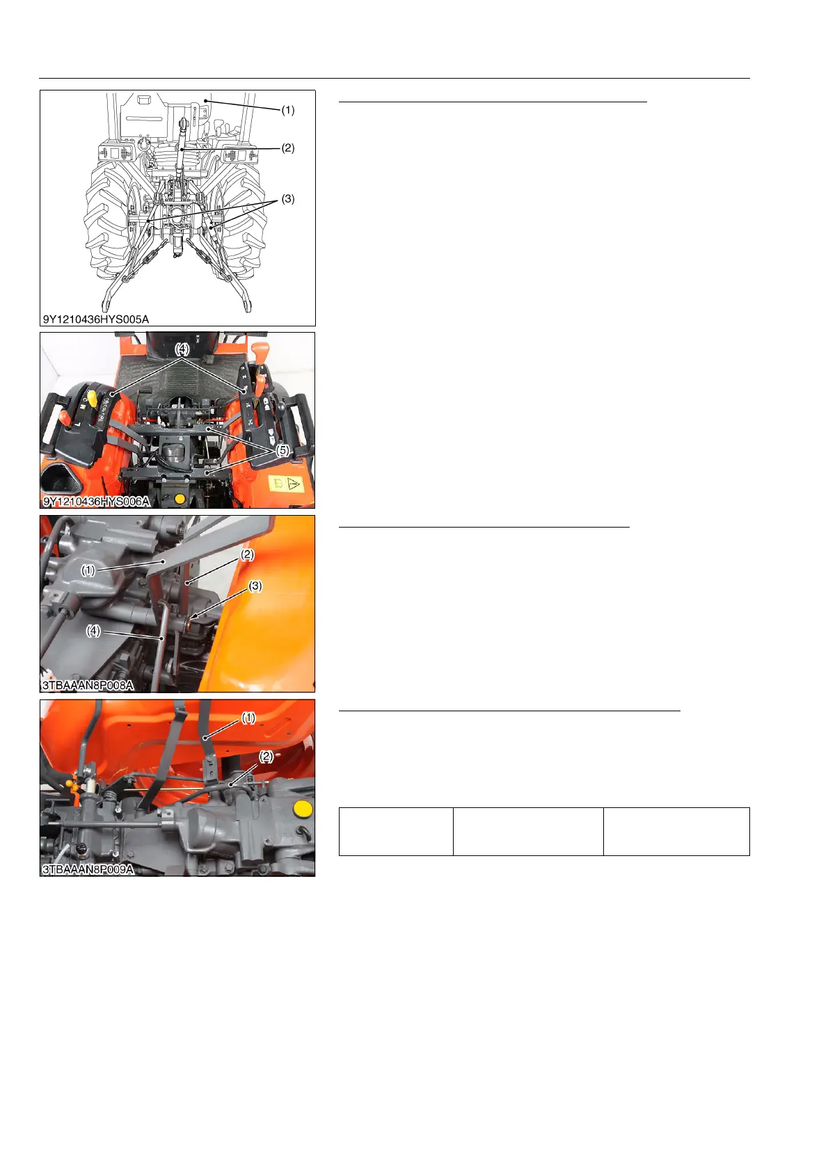
Seat, Top Link, Lever Guides and Seat Bracket
1. Remove the seat (1) and seat under cover.
2. Remove the top link (2) and disconnect the lift rods (3).
3. Remove the lever grips and lever guides (4).
4. Remove the seat brackets (5).
9Y1210436HYS0009US0
PTO Shift Lever and Range Gear Shift Lever
1. Remove the PTO rod (4).
2. Remove the external snap ring (3) and remove the PTO shift
lever (1) and range gear shift lever (2).
9Y1210436HYS0010US0
3-point Hitch Delivery Pipe, Hydraulic Control Lever
1. Remove the hydraulic control lever (1).
2. Remove the 3-point hitch delivery pipe (2).
3. Remove the pipe clamp and disconnect the 3-point hitch
delivery pipe at hydraulic cylinder block side.
(When reassembling)
9Y1210436HYS0011US0
(1) Seat
(2) Top LInk
(3) Lift Rod
(4) Lever Guide
(5) Seat Bracket
(1) PTO Shift Lever
(2) Range Gear Shift Lever
(3) External Snap Ring
(4) PTO Rod
Tightening torque Delivery pipe joint bolt
50 to 60 N·m
5.1 to 6.1 kgf·m
37 to 44 lbf·ft
(1) Hydraulic Control Lever (2) 3-point Hitch Delivery Pipe


 To Next Page