ELECTRICAL SYSTEM
B2420, WSM
9-S24
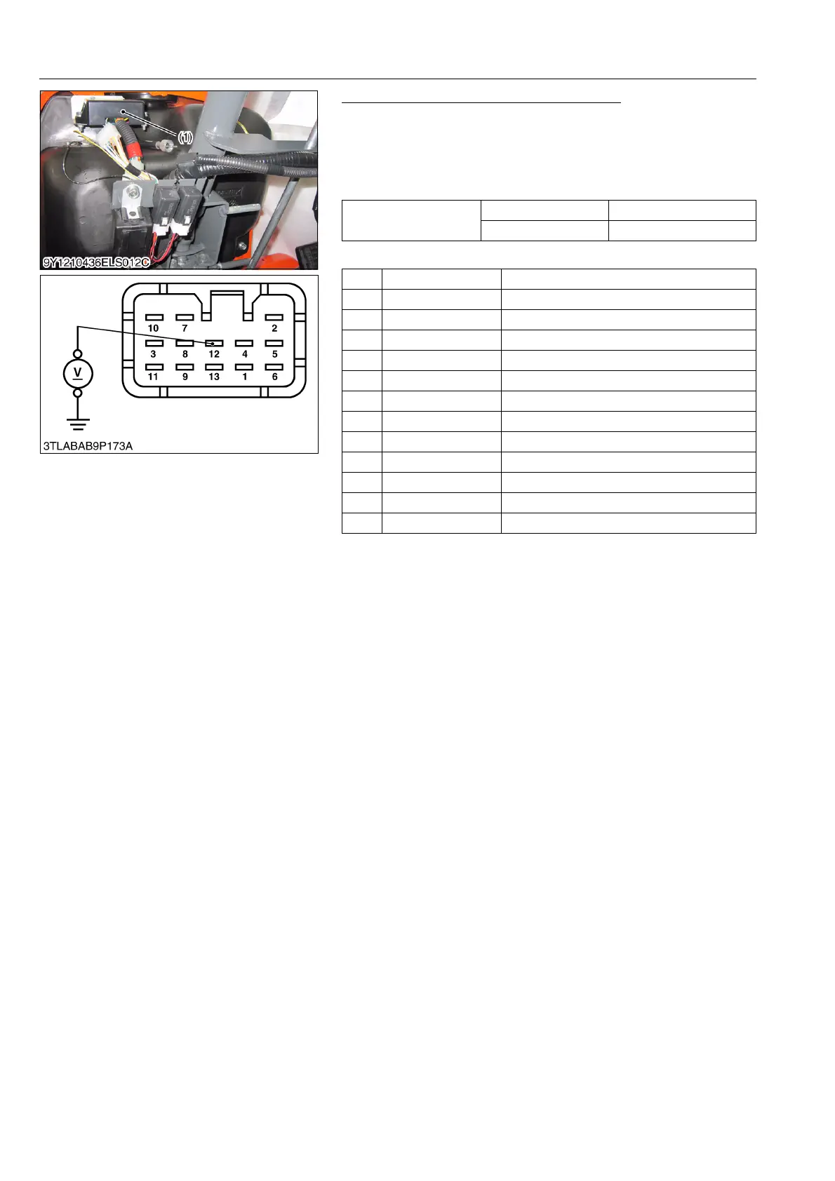
Flasher Unit (Serial Number Above 33598)
1. Disconnect the connector from the flasher unit.
2. Turn the main switch at ON position.
3. Measure the voltage between the terminal 12, 13 and chassis.
4. If the voltage differ from the battery voltage, the wiring harness
is faulty.
(Reference)
Q Flasher Unit Actuation Test
1. Set the hazard switch to the ON position, and make sure the
hazard light gives 60 to 120 flashers for a minute.
2. Set the main switch to the ON position and move the turn signal
switch to the left. Make sure the left-hand light gives flashes.
Then move the turn signal switch to the right and make sure the
right-hand light gives flashes.
3. If both the hazard switch and the turn signal switch and the turn
signal switch function but the above actions do not take place,
replace the flasher unit with new one.
9Y1210436ELS0080US0
Voltage
Ter mi na l 12 – Chassis Approx. battery voltage
Ter mi na l 13 – Chassis Approx. battery voltage
1 ––
2 0.85 L/B Beacon Signal Lamp
3 0.5W/B Beacon Lamp Switch
4 0.85R/Y AC
5 0.85G/OR Turn Signal Lamp (RH)
6 0.5G/R Turn Signal Lamp Switch (RH)
7 0.5B Ground
8 0.85P Turn Signal Lamp (LH)
9 0.5W/G Turn Switch (LH)
10 0.5G/B Trailer Indicator
11 0.5W/L Hazard Switch
12 1.25R/G +B (Hazard)
13 0.85R/L +B (Beacon)
(1) Flasher Unit