ELECTRICAL SYSTEM
B2420, WSM
9-S35
Slip Ring
1. Check the slip ring for score.
2. If scored, correct with an emery paper or on a lathe.
3. Measure the O.D. of slip ring with vernier calipers.
4. If the measurement is less than the allowable limit, replace it.
9Y1210436ELS0018US0
Brush Wear
1. Measure the brush length with vernier calipers.
2. If the measurement is less than allowable limit, replace it.
3. Make sure that the brush moves smoothly.
4. If the brush is defective, replace it.
9Y1210436ELS0019US0
Rectifier
1. Check the continuity across each diode of rectifier with an
analog ohmmeter. Conduct the test in the (R x 1) setting.
2. The rectifier is normal if the diode in the rectifier conducts in one
direction and does not conduct in the reverse direction.
• Do not use a 500 V megger for measuring because it will
destroy the rectifier.
• Do not use an auto digital multimeter. Because it's very
hard to check the continuity of rectifier by using it.
9Y1210436ELS0020US0
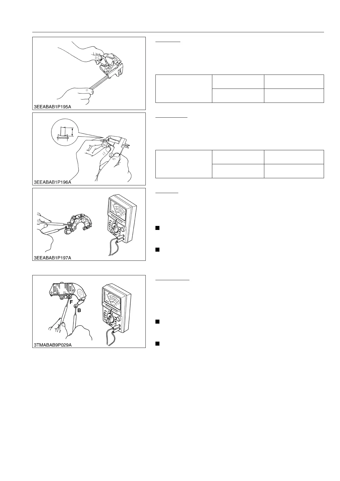
IC Regulator
1. Check the continuity across the B terminal and the F terminal of
IC regulator with an analog ohmmeter. Conduct the test in the
(R x 1) setting.
2. The IC regulator is normal if the IC regulator conducts in one
direction and does not conduct in the reverse direction.
• Do not use a 500 V megger for measuring because it will
destroy the IC regulator.
• Do not use an auto digital multimeter. Because it is very
hard to check the continuity of IC regulator by using it.
9Y1210436ELS0021US0
Slip ring O.D.
Factory specification
14.4 mm
0.567 in.
Allowable limit
14.0 mm
0.551 in.
Brush length
Factory specification
10.5 mm
0.413 in.
Allowable limit
8.4 mm
0.331 in.