Home
Yanmar
Engine
3JH3E
Page 128 (1-5 Sectional view)
Yanmar 3JH3E - 1-5 Sectional view
284 pages
Manual
Save Page as PDF
To Next Page
To Next Page
To Previous Page
To Previous Page
Loading...
Chapter
7
Reduction
and
Reversing
Gear
~l.:...
,::C,:;:;on:.:;s:;;.:t;.;:;,,r.::,uc,:;;,;t:;.:,;io~n,;.._
___________________________
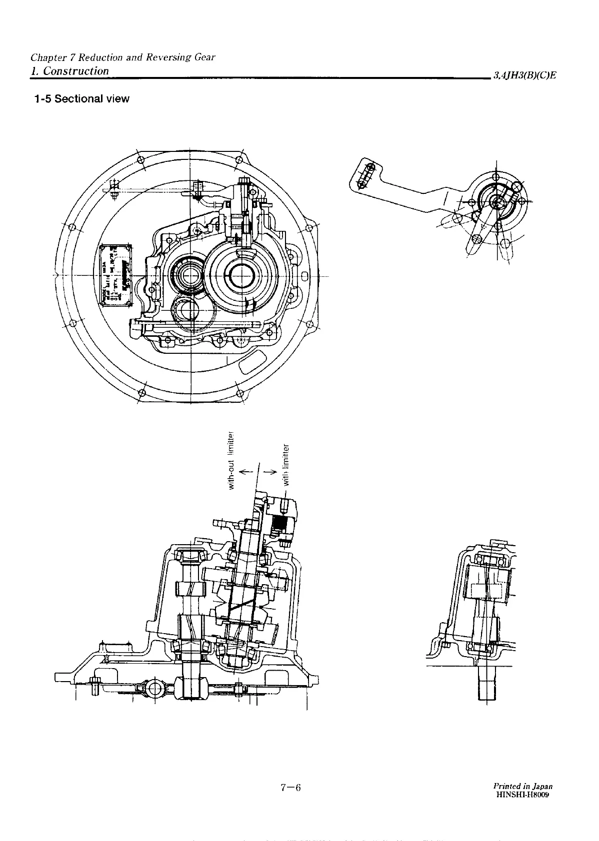
3,4JH3(B)(C)E
1-5
Sectional
view
7-6
Printed
in
Japan
HINSHI-H8009
127
129
Table of Contents
Main Page
COVER
1
FOREWORD
2
INDEX
3
Chapter 1 GENERAL
4
1. Exterior Views
5
1-1 3JH3E
5
1-2 4JH3E
6
2. Specifications
7
2-1 3JHE,3JH3BE,3JH3CE
7
2-2 4JH3E,4JH3BE,4JH3CE
8
2-3 Sales condition,Marine gear
9
3. Engine Outline
10
3-1 3JH3E(with KM3P Marine gear)
10
3-2 3JH3BE(with KM3A Marine gear)
11
3-3 4JH3E(with KM3A Marine gear)
12
3-4 4JH3BE(with KM3A Marine gear)
13
4. Piping Diagrams
14
4-1 3,4JH3(B)(C)E
14
Chapter 2 INSPECTION AND SERVICING OF BASIC ENGINE PARTS
15
1. Cylinder Block
16
1-1 Inspection of parts
16
1-2 Cleaning of oil holes
16
1-3 Color check procedure
16
1-4 Replacement of cup plugs
17
1-5 Cylinder bore measuremant
18
2. Cylinder Head
19
2-1 Inspecting the cylinder head
20
2-2 Valve seat correction procedure
21
2-3 Intake/exhaust valves, valve guides
21
2-4 Valve springs
23
2-5 Assembling the cylinder head
24
2-6 Measuring top clearance
24
2-7 Intake and exhaust valve head clearance
24
2-8 Adjustment of valve head clearance
25
3. Piston and Piston Pins
26
3-1 Piston
27
3-2 Piston Pin
27
3-3 Piston rings
28
4. Connecting Rod
30
4-1 Inspecting the connection rod
30
4-2 Crank pin bushing
31
4-3 Piston pin bushing
31
4-4 Assembling piston and connecting rod
32
5. Crankshaft and Main Bearing
33
5-1 Crankshaft
33
5-2 Main bearing
35
6. Camshaft and Tappets
36
6-1 Camshaft
36
6-2 Tappets
37
7. Timing Gear
39
7-1 Inspecting the gears
39
7-2 Gear timing marks
40
8. Flywheel and Housing
41
8-1 Specifications of flywheel
41
8-2 Dimensions of flywheel and mounting flange
42
8-3 Ring gear
43
8-4 Position of top dead center and fuel injection timing
43
8-5 Damper disk and cooling fan
44
Chapter 3 FUEL INJECTION EQUIPMENT
45
1. Fuel Injection Pump Service Data
46
1-1 3JH3(B)(C)E
46
1-2 4JH3(B)(C)E
46
2. Governor
49
2-1 Cold start knob(For 4JH3(B)(C)E only)
49
2-2 Disassembly Reassembly and Inspection of Governor
51
2-3 Assembling governor
55
3. Disassembly, Reassembly and Inspection of Fuel Injection pump
59
3-1 Disassembly of fuel injection pump
60
3-2 Inspection of fuel injection pump
64
3-3 Reassembly of fuel injection pump
65
4. Adjustment of Fuel Injection Pump and Govemor
69
4-1 Preparations
69
4-2 Adjustment of top clearance
70
4-3 Adjusting of injection timing
71
4-4 Plunger pressure test
72
4-5 Delivery valve pressure test
72
4-6 Adjusting injection volume(uniformity of each cylinder)
72
4-7 Adjustment of govenar
73
5. Fuel Feed Pump
75
5-1 Construction of fuel feed pump
75
5-2 Fuel feed pump specifications
75
5-3 Disassembly and reassembly of fuel feed pump
76
5-4 Plunger pressure test
76
6. Fuel Injection Nozzle
77
6-1 Function of fuel injection nozzle
77
6-2 Fuel injection nozzle disasembly
78
6-3 Fuel injection nozzle inspection
78
6-4 Fuel injection nozzle reassembly
79
6-5 Adjusting fuel injection nozzle
80
7. Trouble shooting of fuel injection pump
81
7-1 Troubleshooting of fuel injection pump
81
7-2 Major faults and troubleshooting
81
8. Tools
83
9. Fuel Filter
85
9-1 Fuel filter specifications
85
9-2 Fuel filter inspection
85
10. Fuel Tank
86
11.Troubleshooting
87
Chapter 4 INTAKE AND EXHAUST SYSTEM
90
1. Intake System
91
2. Exhaust System
92
2-1 Construction
92
2-2 Mixing elbow inspection
92
Chapter 5 LUBRICATION SYSTEM
93
1. Lubrication System
94
2. Lube Oil Pump
95
2-1 Lube oil pump construction
95
2-2 Specifications of lube oil pump
96
2-3 Lube oil pump disassembly
97
2-4 Lube oil pump inspection
97
2-5 Oil pressure regulating valve construction
98
3. Lube Oil Filter
99
3-1 Lube oil filter construction
99
3-2 Lube oil filter replacement
100
4. Lube Oil Cooler
101
4-1 Lube oil cooler construction
101
4-2 Inspecting the lube oil cooler
101
5. Rotary Waste Oil Pump (Optional)
102
5-1 Construction
102
5-2 Inspecting the waste oil pump
102
Chapter 6 COOLING WATER SYSTEM
103
1. Cooling Water System
104
2. Sea Water Pump
106
2-1 Specifications of sea water pump
106
2-2 Sea water pump disassembly
106
2-3 sea water pump Inspection
106
2-4 Sea water pump reassenbly
107
2-5 Current characeristics
107
3. Fresh Water Pump
108
3-1 Fresh water pump construction
108
3-2 Specifications of fresh water pump
109
3-3 Fresh water pump disassembly
109
3-4 Fresh water pump inspection
109
4. Heat Exchaniger
111
4-1 Heat exchanger construction
111
4-2 Specifications of heat exchanger
112
4-3 Disasembly and reassenbly of the heat exchanger
112
4-4 Heat exchanger inspection
112
5. Pressure Cap and Sub Tank
113
5-1 Pressure cap construction
113
5-2 Pressure cap pressure control
113
5-3 Pressure cap inspection
113
5-4 Funktion of the sub tank
113
5-5 Specifications of sub tank
114
5-6 Mounting the sub tank
114
5-7 Precautions on usage of the sub tank
114
6. Thermostat
115
6-1 Funktion of thermostat
115
6-2 Thermostat construction
115
6-3 Characteristics of thermostat
115
6-4 Thermostat inspection
116
6-5 Testing the thermostat
116
7. Bilge Pump and Bilge Strainer (Optional)
117
7-1 Introductin
117
7-2 Description
117
7-3 Cautions
117
Chapter 7 REDUCTION AND REVERSING GEAR
122
Marine Gear Models [KM3A]
123
1. Construction
123
1-1 Construction
123
1-2 Specifications
124
1-3 Power transmission system
125
1-4 Drawing
127
1-5 Sectional view
128
2. Shifting Device
129
2-1 Construction of shifting mechanism
129
2-2 Forward and reverse clutch operation
130
2-3 Engagement and disengagement of clutch
130
2-4 Clutch shifting force
131
2-5 Adjustment of shifting device
131
2-6 Adjustment of the remoto control head
133
2-7 Cautions
133
3. Inspection and Servicing
134
3-1 Clutch case
134
3-2 Bearing
134
3-3 Gear
134
3-4 Forward and reverse large gears
134
3-5 Drive cone
134
3-6 Trust collar
136
3-7 Cup spring
137
3-8 Oil seal of out put shaft
137
3-9 Input shaft
137
3-10 Out put shaft
137
3-11 Intermediate shaft
138
3-12 Shifting device
138
3-13 Damper disk
139
3-14 Shim adjustment for output and input shafts
139
3-15 Torque limiter
141
4. Disassembly
142
4-1 Dismanting the clutch
142
4-2 Removal of the output shaft
144
4-3 Removal of the ointermediate shaft
146
4-4 Dismanting the shifting device
146
5. Reassembly
147
5-1 Reassembly of output shaft
147
5-2 Reassembly of the clutch
148
5-3 Reassembly of the shiating device
150
Marine Gear Models [KM3P4]
151
1. Construction
151
1-1 Construction
151
1-2 Specifications
152
1-3 Power transmission system
153
1-4 Drawing
155
1-5 Spectional view
156
2. Shifting Device
157
2-1 Construction of shifting mechanism
157
2-2 Forward and reverse clutch operation
158
2-3 Engagement and disengagement of clutch
158
2-4 Clutch shifting force
159
2-5 Adjustment of the remoto control head
159
2-6 Adjustment of the remoto control head
161
2-7 Cautions
161
3. Inspection and Servicing
162
3-1 Clutch case
162
3-2 Bearing
162
3-3 Gear
162
3-4 Forward and reverse large gears
162
3-5 Drive cone
162
3-6 Thrust collar
164
3-7 Cup spring and spring retainer
165
3-8 Oil seal of output shaft
165
3-9 Input shaft
165
3-10 Output shaft
165
3-11 Intermediate shaft
166
3-12 Shifting device
166
3-13 Damper disk
167
3-14 Shim adjustment for output and input shafts
167
3-15 Torque limiter
169
4. Disassembly
170
4-1 Dismantling the clutch
170
4-2 Removal of the output shaft
172
4-3 Removal of the intermediate shaft
173
4-4 Dismanting the shifting device
174
5. Reassembly
175
5-1 Reassembly of output shaft
175
5-2 Reassembly of the clutch
176
5-3 Reassembly of the shiating device
178
Chapter 8 REMOTE CONTROL (OPTIONAL)
179
1. Remote Control System
180
1-1 Construction of remoto control system
180
1-2 Remoto control device components
180
2. Remote Control Installation
181
2-1 Speed control
181
2-2 Clutch control
181
2-3 Engine stop
182
3. Remote Control Inspection
183
4. Remote Control Adjustment
184
Chapter 9 ELECTRICAL SYSTEM
185
1. Electrical System
186
1-1 System diagram of electric parts(B-type)
186
1-2 Wiring diagram
188
2. Battery
190
2-1 Construction
190
2-2 Battery capacity and battery cables
190
2-3 Inspection
190
2-4 Charging
192
2-5 Battery storage precautions
192
3. Starter Motor
193
3-1 Specifications
193
3-2 The planatary gear starter system
193
3-3 Removal
194
3-4 Trouble mooting the starter system
195
3-5 Disassembly
196
3-6 Inspection and Repair
200
3-7 Reasembly
205
3-8 Operation Specifications Check
206
4. Alternator Standard, 12V/55A
207
4-1 Features
207
4-2 Specifications
207
4-3 Characteristics
207
4-4 Construction
208
4-5 Aiternator functioning
209
4-6 Handling precautions
209
4-7 Disassemblling the alternator
210
4-8 Inspection and adjustment
211
4-9 Reassembling the alternator
213
4-10 Performance test
214
5. Alternator 12V/80A (OPTIONAL)
215
5-1 Features
215
5-2 Specifications
215
5-3 Characteristics
215
5-4 Construction
216
5-5 Alternator functioning
217
5-6 Handling precautions
217
5-7 Disassembling the alternator
218
5-8 Inspection and adjustment
219
5-9 Reassembling the alternator
221
5-10 Performance test
222
5-11 Troubleshooting
223
6. Instrument Panel
225
6-1 B2-type instrument panel with wiring
225
6-2 C-type instrument panel
225
6-3 Extension codes
226
7. Waming Devices
227
7-1 Oil pressure alarm
227
7-2 Cooling water temperature alarm
228
7-3 Sender unit for lube oil pressure gauge
228
7-4 Sender unit Oor the cooling water temperature gauge
229
8. Air Heater (Optional)
230
9. Electric type Engine Stopping Device (Optional)
231
9-1 Solenoid
231
9-2 Relay
232
9-3 Wire harness of engine stop
232
10. Tachometer
233
10-1 Construction of tachometer
233
10-2 Specifications and dimensions of tachometer
233
10-3 Measurement of sensor unit characteristics
234
Chapter 10 DISASSEMBLY AND REASSEMBLY
236
1. Disassembly and Reassembly Precautions
237
2. Disassembly and Reassembly Tools
238
2-1 General handtools
238
2-2 Special Handtools
241
2-3 Measuring Instruments
243
2-4 Other material
244
2-5 Measuring Instruments
247
3. Disassembly and Reassembly
250
3-1 Disassembly
250
3-2 Reassembly
259
4. Table of Standard Measurements for Maintenance
271
4-1 Cylinder head
271
4-2 Cylinder block
272
4-3 Valve equipment
272
4-4 Piston
273
4-5 Piston ring
273
4-6 Connecting rod
274
4-7 Cam shaft
274
4-8 Crank shaft
274
4-9 Side clearance and backlash
275
4-10 Miscellaneous
275
5. Tightening torque
276
5-1 Main Bolt and Nut
276
5-2 Standard Bolts and Nuts(without lubricant)
276
6. Test running
277
6-1 Preliminary Precautions
277
6-2 Check Points and Precautions During Running
277
Chapter 11 TROUBLESHOOTING
278
1. Troubleshooting
279
BACK COVER
284
Other manuals for Yanmar 3JH3E
Operation Manual
48 pages
Related product manuals
Yanmar 3JH3CE
48 pages
Yanmar 3JH3BE
48 pages
Yanmar 3JH3(8)E
48 pages
Yanmar 3JH5E
160 pages
Yanmar 3JH4E
142 pages
Yanmar 3JH40
198 pages
Yanmar 3JH4CE
214 pages
Yanmar 3JH4BE
214 pages
Yanmar 3JH2 Series
308 pages
Yanmar 3YM30
114 pages
Yanmar 3TNV88
142 pages
Yanmar 3TNV70
264 pages