Chapter 3 Fuel Injection
Equipment
.;;4.;..
•
.;.;A;..;d.;::.j.;..u.;..st.;..m_e_n_t_o_f_F_u_el_I_n_j_ec_t_io_n_P_u_m_p
__
a_n_d_G_o_v_e_r_n_o_r
______________
3,4JH3(B)(CJE
(5)
Check control rack stroke
Make
sure
the
rack
position
is at
11.5~12.5mm
(0.4527~0.4921 in.) on the indicator scale when the
governor control lever
is
set at the maximum operating
position.
If
it
is not at this valve, change the link connecting the
governor and control rack
to
adjust it.
NOTE:
Links are availabe
in
1mm (0.0394in.) increments.
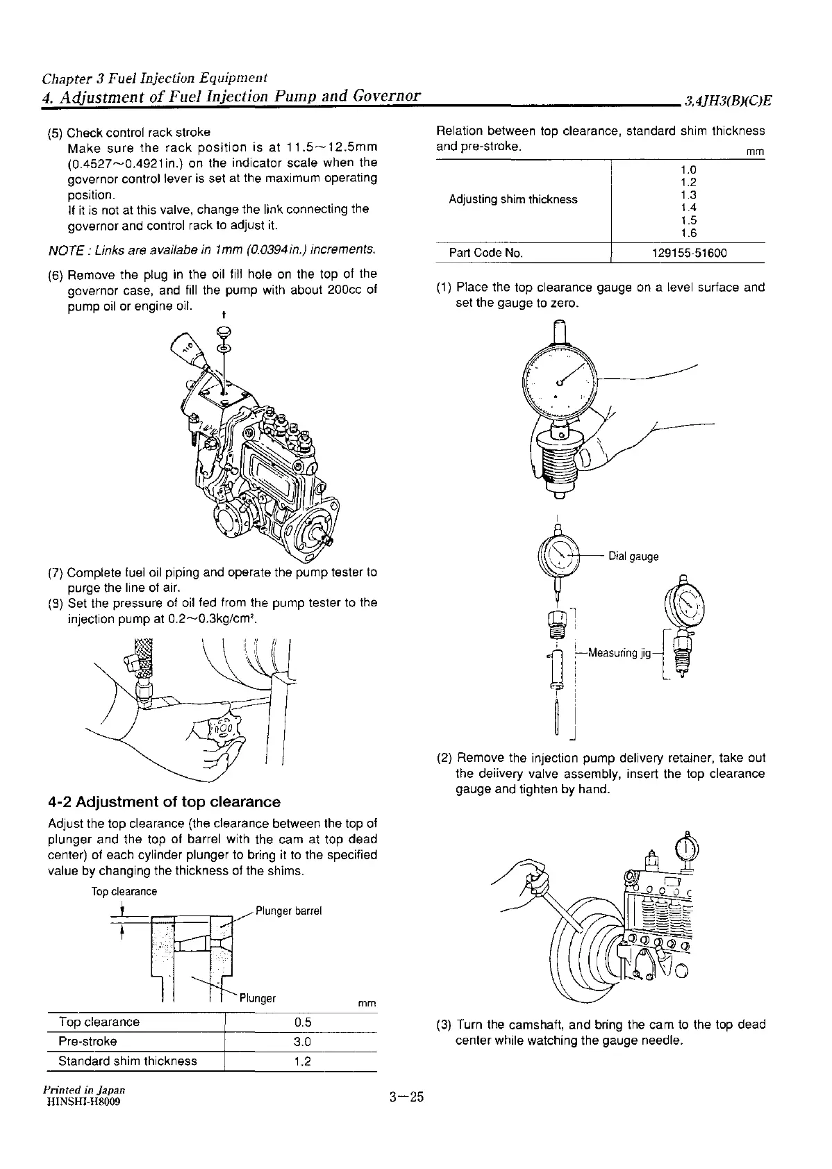
(6)
Remove the plug
in
the
oil
fill hole
on
the top of the
governor case, and fill the pump with about 200cc of
pump
oil
or engine oil.
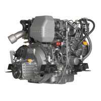
(7)
Complete fuel
oil
piping and operate the pump tester
to
purge the line
of
air.
(S)
Set the pressure of
oil
fed from the pump tester to the
injection pump at 0.2~0.3kg/cm
2
•
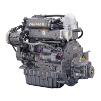
4-2 Adjustment of top clearance
Adjust the top clearance (the clearance between the top of
plunger and the top of barrel with the cam at top dead
center) of each cylinder plunger to bring it
to
the specified
value
by
changing the thickness of the shims.
Top
clearance
_l_
t
Top clearance
Pre-stroke
Standard shim thickness
Printed
in Japan
HINSHI-H8009
Plunger
barrel
mm
0.5
3.0
1.2
3-25
Relation between top clearance, standard shim thickness
and pre-stroke.
Adjusting
shim
thickness
Part Code No.
1.0
1.2
1.3
1.4
1.5
1.6
129155-51600
mm
(1)
Place the top clearance gauge
on
a level surface and
set the gauge to zero.
(2)
Remove the injection pump delivery retainer, take out
the deiivery valve assembly, insert the top clearance
gauge and tighten by hand.
(3)
Turn the camshaft, and bring
the
cam
to
the top dead
center while watching the gauge needle.