Chapter 9 Electrical System
_2_.
B_at_te_r.;.y
____________________________
3,4]H3(B)(C)E
2.
Battery
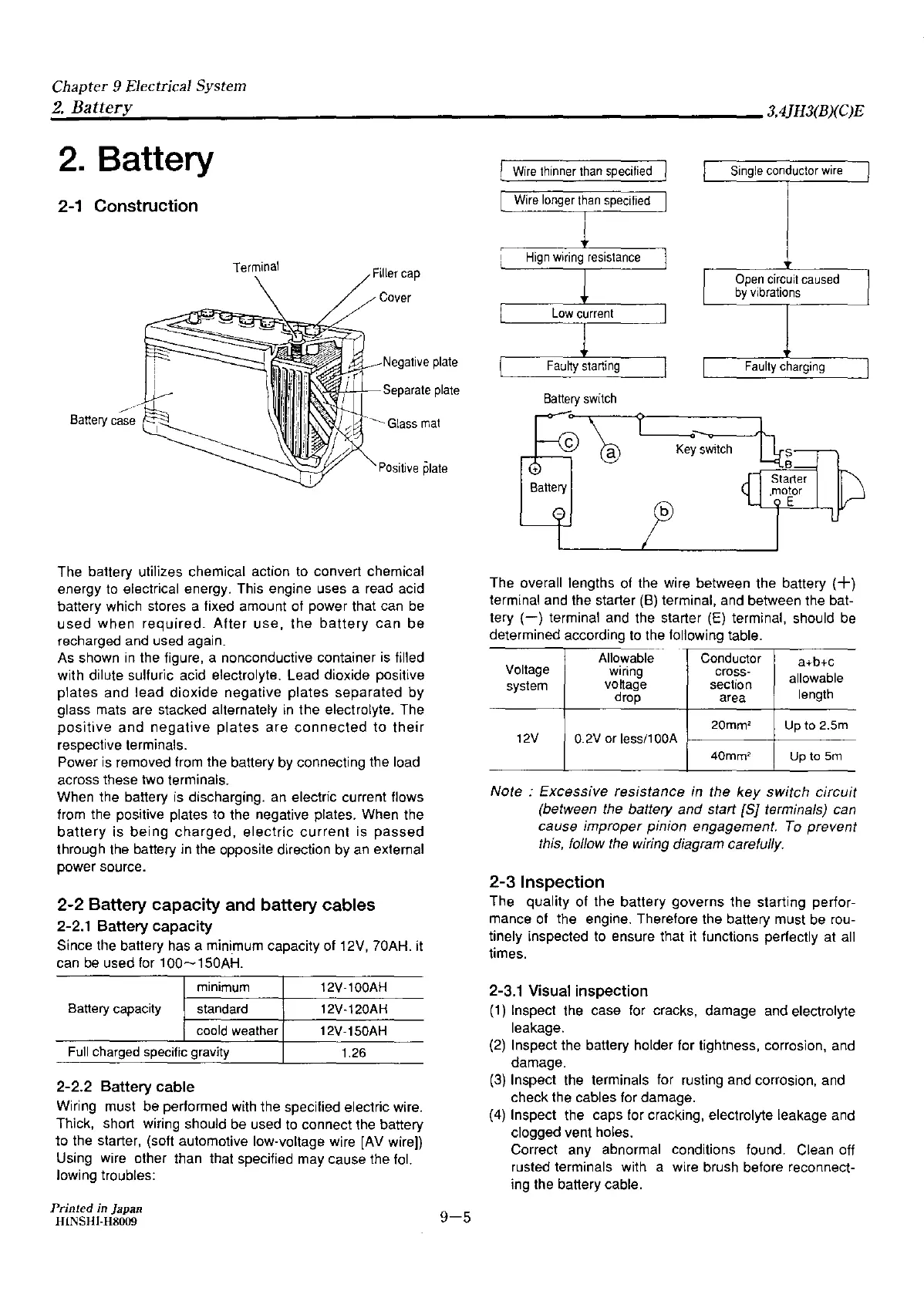
2-1 Construction
Terminal
Filler
cap
Cover
Negative
plate
,.,.,l;l-,L,___.__~
Separate
plate
Battery
c~~
Glass
mat
Positive
plate
The battery utilizes chemical action to convert chemical
energy to electrical energy. This engine uses a read acid
battery which stores a fixed amount of power that can
be
used
when
required.
After
use,
the
battery
can
be
recharged and used again.
As
shown
in
the figure, a nonconductive container
is
filled
with dilute sulfuric acid electrolyte. Lead dioxide positive
plates and lead dioxide negative plates separated by
glass mats are stacked alternately
in
the electrolyte. The
positive
and
negative
plates
are
connected
to
their
respective terminals.
Power
is
removed from the battery
by
connecting the load
across these two terminals.
When the battery
is
discharging.
an
electric current flows
from the positive plates to the negative plates. When the
battery
is
being
charged,
electric
current
is
passed
through the battery in the opposite direction
by
an
external
power source.
2-2 Battery capacity and battery cables
2-2.1 Battery capacity
Since the battery has a minimum capacity of 12V, 70AH. it
can
be
used for 100~150AH.
minimum
12V-100AH
Battery
capacity
standard
12V-120AH
coold
weather
12V-150AH
Full
charged
specific
gravity
1.26
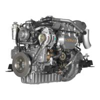
2-2.2 Battery cable
Wiring must be performed with the specified electric wire.
Thick, short wiring should
be
used to connect the battery
to !he st~rter, (soft automotive low-voltage wire
[AV
wire)}
Using wire other than that specified may cause the
fol.
lowing troubles:
Printed in Japan
H!NSHl-H8009
9-5
[
Wire
thinner
than
specified
Wire
longer
than
specified
Hign
wiring
resistance
Low
current
Faulty
starting
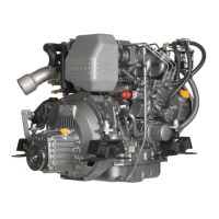
Ba1tery
switch
Single
conductor
wire
Open
circuit
caused
by
vibrations
Faulty
charging
The overall lengths
of
the wire between the battery
(+)
terminal and the starter (8) terminal, and between the bat-
tery
(-)
terminal and the starter
(E)
terminal, should
be
determined according to the following table.
Allowable
Conductor
a+b+c
Voltage
wiring
cross-
allowable
system
voltage
section
drop
area
length
20mm'
Up
to
2.Sm
12V
0.2V
or
less/1
ODA
40mm'
Up
to
5m
Note : Excessive resistance in the
key
switch
circuit
(between the battery and start
[SJ
terminals) can
cause improper pinion engagement.
To
prevent
this, follow the wiring diagram carefully.
2-3 Inspection
The quality of the battery governs the starting perfor-
mance of the engine. Therefore the battery must
be
rou-
tinely inspected to ensure that it functions perfectly at all
times.
2-3.1
Visual inspection
(1)
Inspect the case for cracks, damage and electrolyte
leakage.
(2)
Inspect the battery holder for tightness, corrosion, and
damage.
(3}
Inspect the terminals for rusting and corrosion, and
check the cables for damage.
(4)
Inspect the caps for cracking, electrolyte leakage and
clogged vent holes.
Correct any abnormal conditions found. Clean off
rusted terminals with a wire brush before reconnect-
ing the battery cable.