Chapter 9 Electrical System
4.
Alternator
_____________________________
3,4JH3(B)(C)E
4-
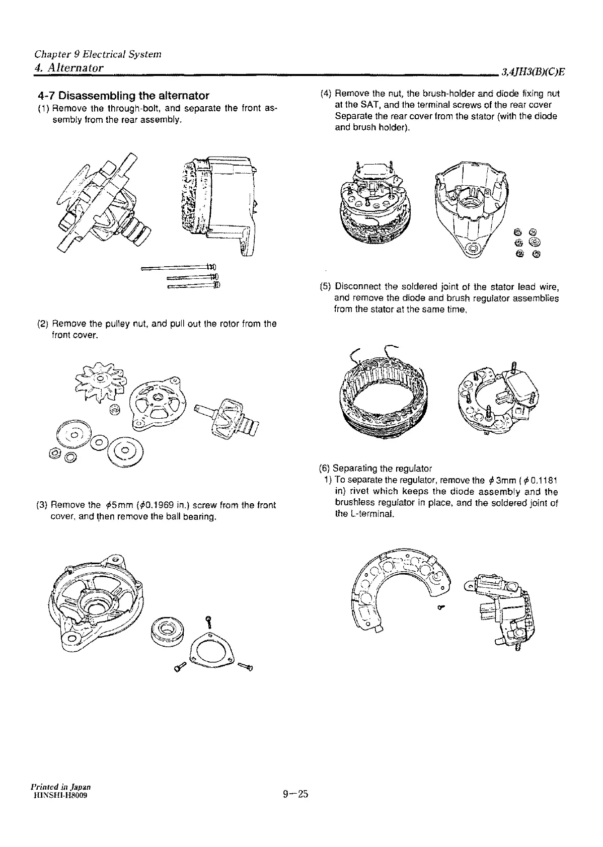
7 Disassembling the alternator
(1) Remove the through-bolt, and separate the front as-
sembly from the rear assembly.
=•
====\100
,::::~•====iD
(2) Remove the pulley nut, and pull
out
the rotor from the
front cover.
(3} Remove the ¢,5mm
{.,-b0.1969
in.) screw from the front
cover, and then remove the ball bearing.
Printed in Japan
HINSHJ.H8009
9-25
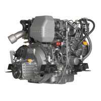
(4) Remove the nut, the brush-holder
and
diode fixing nut
at the SAT,
and
the terminal screws of the rear cover
Separate the rear cover from the stator
(with
the diode
and brush holder).
@I®
@®
@®
(5) Disconnect the soldered joint
of
the stator lead wire,
and remove the diode and brush regulator assemblies
from the stator at the same time,
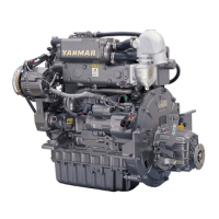
{6)
Separating the regulator
1)
To
separate the regulator, remove the
,t,
3mm (
¢,
0.1181
in)
rivet
which
keeps
the
diode
assembly
and
the
brush!ess regufator in place,
and
the soldered jo[nt
of
the L-termrnaL