Chapter 6 Cooling Water System
.::;;5.:.,;.
P;..;..re;;.;;s;.;.s;;;ur;;.;e;...;;.C~ap:;..;;.a_n
.....
d
.....
S
.....
u_b_T_a_n_k
_____________________
3,4JH3(B)(C)E
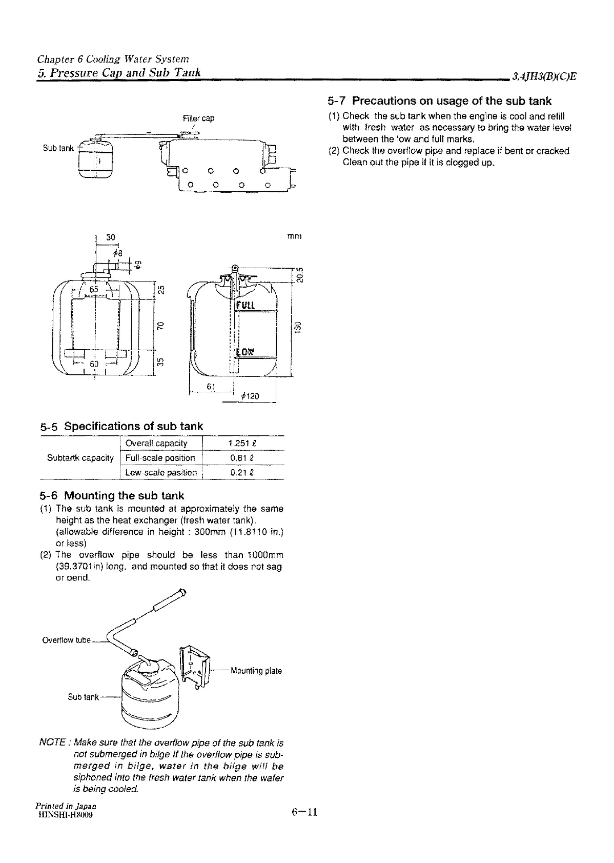
Subtanke!J
,_
30
Filler
cap
/
mm
-----~m
d
!
'-::::,:--,---+
0J
0
r--
5-5
Specifications of sub tank
Overall capacity
Subtartk
capacity Full-scale positiOn
low-scale
pasition
5-6
Mounting the sub tank
61
1120
1251 t
0,81 Q
0.21 Q
{1)
The sub tank is mounted at approximately the same
height as the heat exchanger (fresh water tank).
(allowable difference in height : 300mm (11.8110 in.)
or less)
(2)
The
overflow pipe should
be
less than 1000mm
{39.370i in) long. and mounted so that it does not sag
or oend,
Sub
lank
NOTE : Make sure that the overflow pipe
of
the sub tank is
not submerged in bilge
If the overflow pipe is sub-
merged
in
bilge,
water
in
the
bilge
will
be
siphoned into the fresh water tank when the wafer
is
being cooled.
Printed
in Japan
HINSHr-H8009
6-11
5-7 Precautions on usage
of
the sub tank
(1)
Check the sub tank when the engine is cool and refill
with fresh water as necessary to bring the water level
between the tow and fult marks,
(2) Check the overflow pipe and replace
if
bent
or
cracked
Cfean out the pipe
if
it is dogged up.