Chapter 9 Electrical
System
.;;,1.;;.;0.;...;;.T,;;.ac;;;.;;h,;;.;;o.;;;;m;;;.;e;.;.t.;.;er;...._
__________________________
3,4JH3(B)(C)E
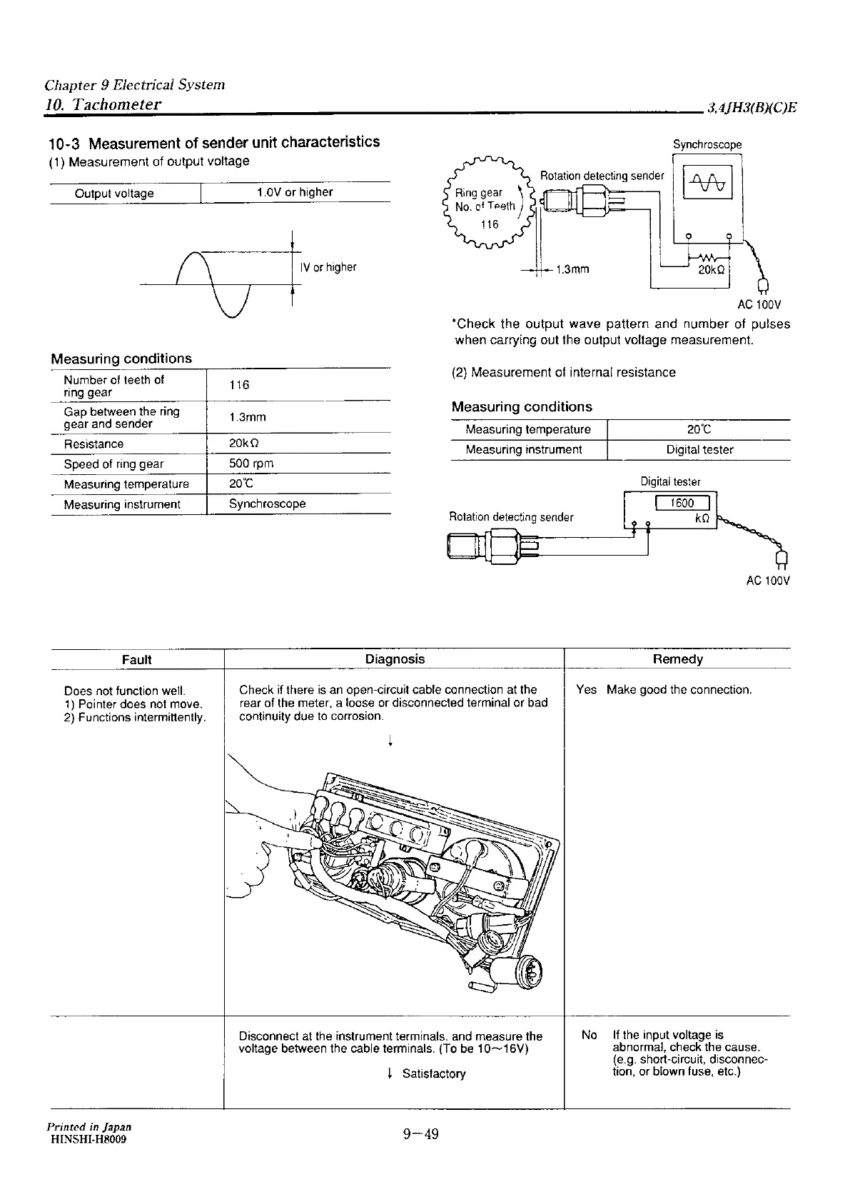
10-3 Measurement
of
sender unit characteristics
(1)
Measurement
of
output
voltage
Synchroscope
Output voltage 1.0V or higher
Measuring conditions
Number of teeth of
ring gear
Gap between the ring
gear and sender
Resistance
Speed of ring gear
Measuring temperature
Measuring instrument
Fault
Does not function well.
1)
Pointer does not move.
2) Functions intermittently.
Printed
in japan
HINSHI-H8009
IV
or
higher
116
1.3mm
20kO
500 rpm
20°C
Synchroscope
Diagnosis
AC
100V
•check
the
output
wave
pattern
and
number
of
pulses
when
carrying
out
the
output
voltage
measurement.
(2)
Measurement
of internal resistance
Measuring conditions
Measuring temperature 20'C
Measuring instrument
Digital tester
Digital
tester
Rotation
detecting
sender
AC
100V
Remedy
Check if there
is
an open-circuit cable connection at the
rear of the meter, a loose or disconnected terminal or bad
continuity due to corrosion.
Yes Make good the connection.
Disconnect at the instrument terminals. and measure the
voltage between the cable terminals. (To
be
10~16V)
i Satisfactory
9-49
No
If
the input voltage
is
abnormal, check the cause.
(e.g. short-circuit, disconnec-
tion, or blown fuse, etc.)


 To Next Page