Chapter
7
Reduction and Reversing Gear
.;;;.3•;..l;;,;;n,;;,;;s~p..;,e.;.ct1;;;;;·,;;,,;on~a.;.;n.;;;d,..;S;;..e;.;;r_v
__
ic_i_n.:...g------------------------
3,4JH3(B)(C)E
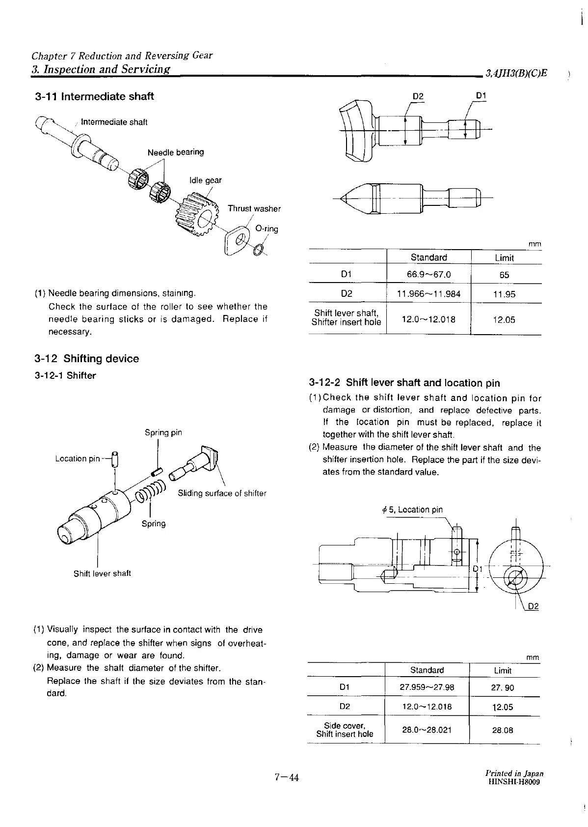
3-11
Intermediate
shaft
Intermediate
shaft
Needle
bearing
Thrust
washer
/
ring
I
"-
(1}
Needle bearing dimensions, staining.
Check the surface of the roller to see whether the
needle bearing sticks or is
damaged.
Replace if
necessary.
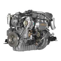
3-12 Shifting device
3-12-1 Shifter
Location
pin--{j
Spring
pin
l~\
©)))))
Sliding
surface
of
shifter
I
Spring
Shilt
lever
shaft
(1)
Visually inspect the surface
in
contact with
the
drive
cone, and replace the shifter when signs of overheat-
ing, damage or wear are found.
(2}
Measure the shaft diameter of the shifter.
Replace the shaft if the size deviates from the stan-
dard.
7-44
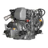
D1
mm
Standard Limit
01
66.9~67.0
65
02
11
.966~
11
.984
11.95
Shift lever shaft,
12.0~12.018
12.05
Shifter insert hole
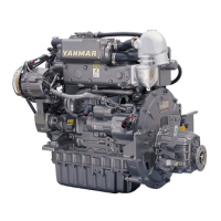
3-12-2 Shift
lever
shaft and location pin
(1
)Check
the
shift
lever
shaft
and
location
pin
for
damage or distortion, and replace defective parts.
If the location pin must be replaced, replace it
together with the shift lever shaft.
(2)
Measure the diameter of the shift lever shaft and the
shifter insertion hole. Replace the part if the size devi-
ates from the standard value.
,f,
5,
Location
pin
Standard
D1
27.959~27.98
D2
12.0~12.018
S'1de
cover,
28.0~28.021
Shift
insert
hole
mm
Limit
27.90
12.05
28.08
Printed in japan
HINSHI-H8009