Chapter 9 Electrical
System
_5
•
...;A~l~t_er_n;.;,;a~to~r...;.(_O_P_T_IO.;.N_A_L..;..)
_____________________
3,4JH3(B)(CJE
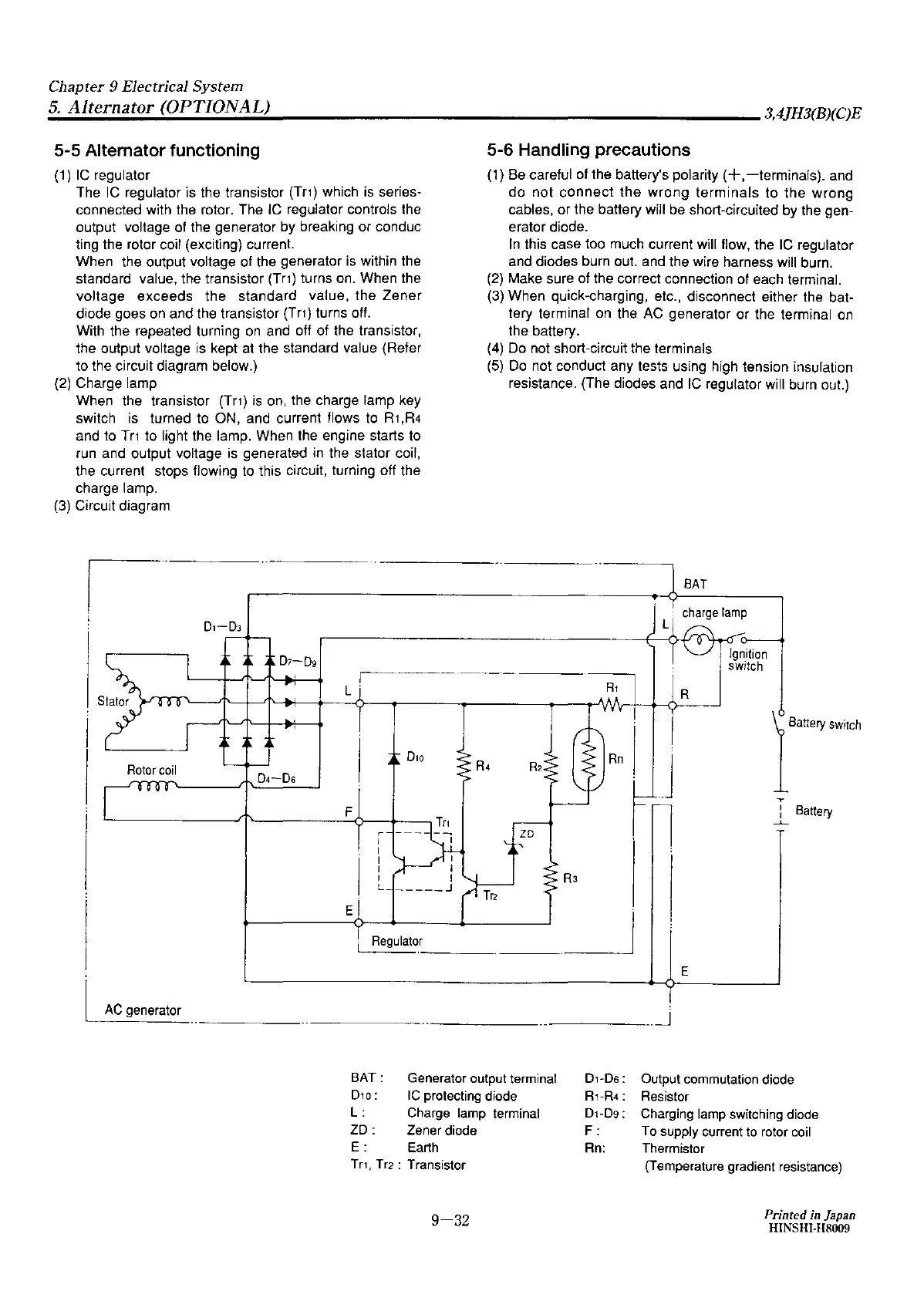
5-5 Alternator functioning
(1) IC regulator
The IC regulator
is
the transistor (Tr1) which is series-
connected with the rotor.
The
IC regulator controls the
output voltage of the
generator
by breaking
or
conduc
ting the rotor coil (exciting) current.
When
the output voltage of the
generator
is within the
standard value, the transistor (Tr1) turns on. When the
voltage
exceeds
the
standard
value,
the
Zener
diode
goes
on and the transistor
(Tn)
turns off.
With the repeated turning on and off of the transistor,
the
output voltage is kept at
the
standard value (Refer
to
the circuit diagram below.)
(2) Charge lamp
When the transistor (Tr1) is on, the charge
lamp
key
switch is
turned
to
ON,
and current flows to
R1
,R4
and to
Tr1
to light the lamp. When the
engine
starts to
run and output voltage is
generated
in the stator coil,
the current stops flowing to this circuit, turning off the
charge lamp.
(3) Circuit
diagram
Rotor
coil
F
r
I
I
I
I
I
L
5-6
Handling precautions
(1) Be careful of
the
battery's polarity
(+,-terminals).
and
do
not
connect
the
wrong
terminals
to
the
wrong
cables,
or
the
battery will be short-circuited
by
the
gen-
erator diode.
In
this
case
too much current will flow, the IC regulator
and
diodes
burn out. and the wire harness will burn.
(2) Make
sure
of the correct connection of each terminal.
(3)
When
quick-charging, etc.,
disconnect
either
the
bat·
tery terminal on
the
AC
generator
or
the terminal on
the
battery.
(4)
Do
not short-circuit the terminals
(5)
Do
not
conduct
any
tests using high tension insulation
resistance. (The diodes and IC regulator will burn out.}
.,.
:
Battery
....._
E
i
RegulaW
_J"
--··
AC
generator
BAT:
Generator output terminal
D1
o :
IC
protecting diode
L :
Charge lamp terminal
ZD:
Zener diode
E:
Earth
Tr1,
Tr2: Transistor
9-32
D1-Ds:
R1-R4:
Dt-D9:
F:
Rn:
E
Output commutation diode
Resistor
Charging lamp switching diode
To
supply current to rotor coil
Thermistor
(Temperature gradient resistance)
Printed in Japan
HINSHI-H8009