Chapter 9 Electrical
System
.;;..3·;...S
__
t_a.;.r.;;.;te_r.;M..;.;..o.;.;;to_r
__________________________
3,4]H3(B)(C)E
3-7 Reassembly
Reassembly is
in
the reverse order of disassembly, how-
ever please note the following points.
1. Tightening Torques : Refer to page 4 of the referece
materials for the tightening
torques of particular screws.
2. The Places to Apply Grease :
(D----The
moving parts of shift lever.
(2)-T--The sliding suriace of magnetic switch plunger.
l--The
sliding surface of pinion.
@----The
tooth of Internal
Gear
and Planet Gear.
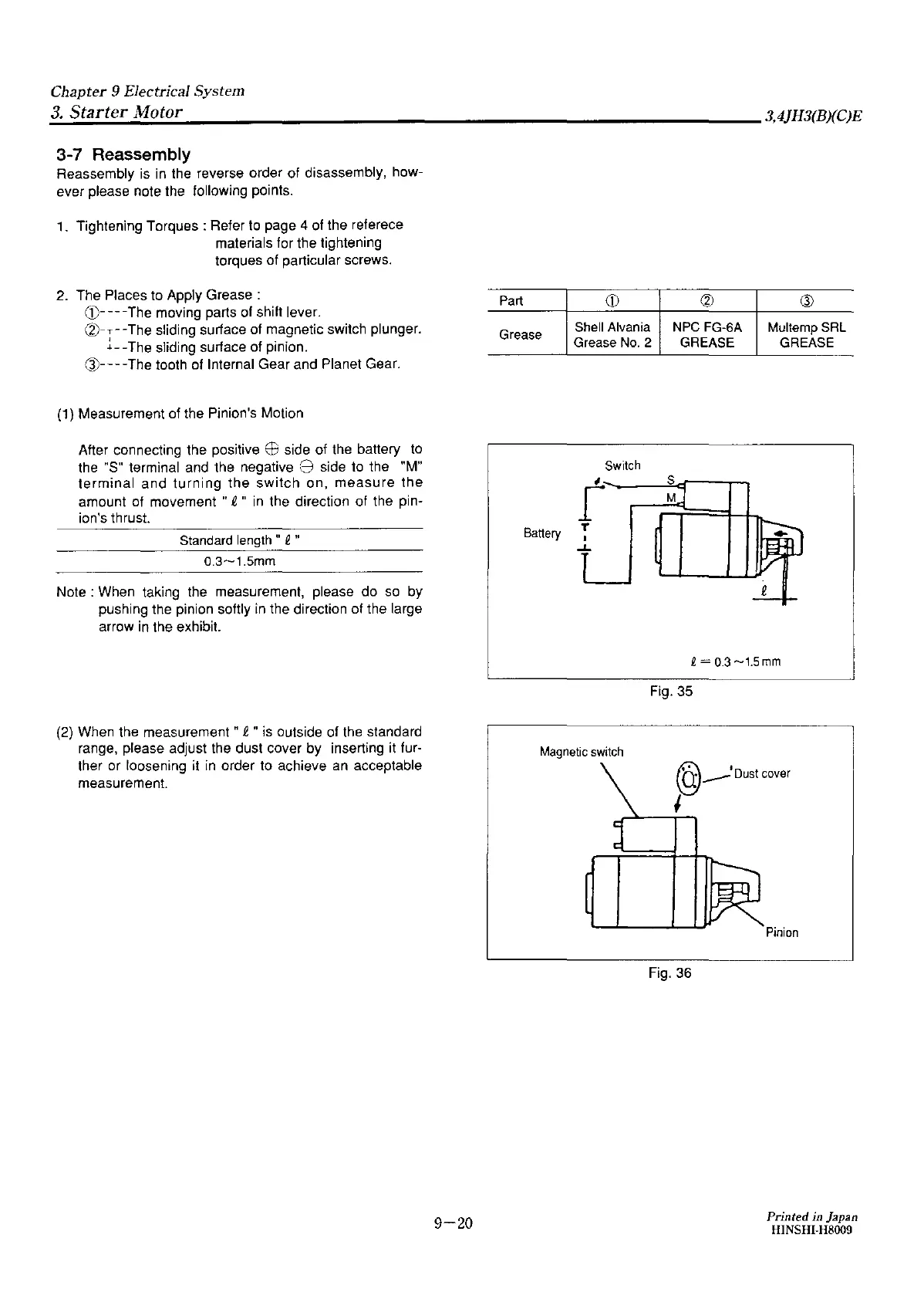
(1) Measurement of the Pinion's Motion
After connecting the positive
EB
side of the battery to
the "S" terminal and the negative
8 side to the "M"
terminal
and
turning
the
switch
on,
measure
the
amount of movement
"R,
" in the direction
of
the pin-
ion's thrust.
Standard length "
2 "
0.3~1.5mm
Note:
When taking the measurement, please do so by
pushing the pinion softly in the direction of the large
arrow in the exhibit.
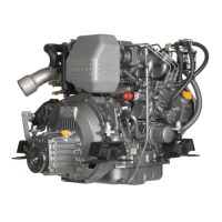
(2) When the measurement "
R,
" is outside of the standard
range, please adjust the dust cover
by
inserting it fur-
ther
or
loosening it in order to achieve an acceptable
measurement.
9-20
Part
(D
(2)
Q)
Grease
Shell Alvania NPC FG-6A
Multemp SRL
Grease No. 2 GREASE GREASE
Switch
t
s
M
Battery
T
J
..L
2
Q =
0.3
~1.5
mm
Fig. 35
Magnetic switch
@--•Dustcover
I
Fig. 36
Pinion
Printed in Japan
HINSHI-H8009