Chapter 7 Reduction and Reversing Gear
.:2::...
S:;;'h~i~ft~in~gi..D~!;;.ev::.!i!::ce;;.....
________________________
3,4]H3(B)(C)E
2-6
Adjustment of the remote control head
Marine
gear
box
control
side
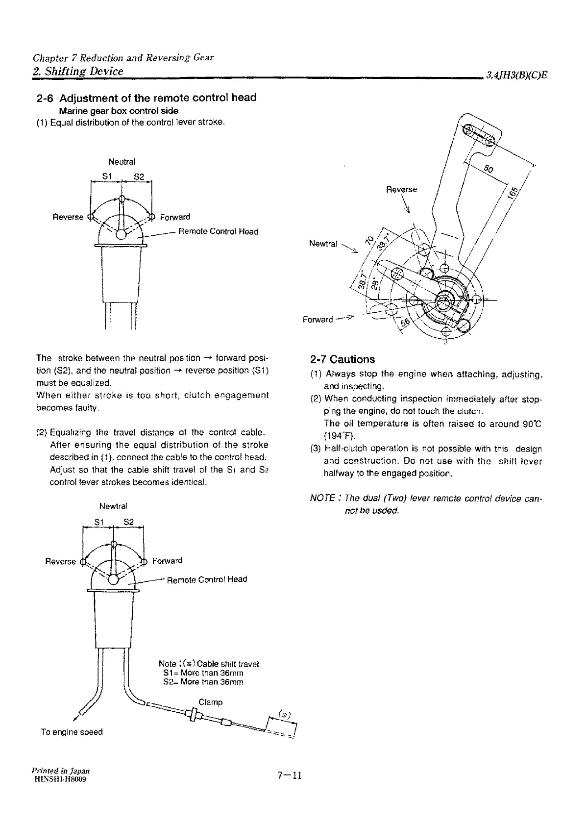
(1) Equal distribution of the control lever stroke.
Neutral
S1
S2
Reverse
Forward
Remote Control
Head
The stroke between the neutral position - forward posi-
tion
(S2), and the neutral position - reverse position {S1)
must be equalized.
When
either
stroke
is
too
short,
clutch
engagement
becomes faulty.
(2) Equalizing the travel distance of the control cable.
After
ensuring
the equal
distribution
of the stroke
described in
(1
),
connect the cable to the control head.
Adjust so that the cable shift travel of the
S1
and
S2
control lever strokes becomes identical.
Newtral
S1
S2
Reverse
/
To
engine
speed
Printed in Japan
Hl;',SHJ-118009
Remote
Control
Head
Note ; (
*)
Cable shift travel
S1
= More than
36mm
S2= More than 36mm
7-11
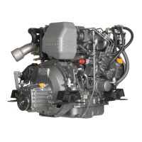
Reverse
<:,
'\
Newtral
~
'-'! c,'b·'
'
I,
,1;;/
·~1
Forward_.-:;;,,-
2-7 Cautions
\
/,,
( \ \
(1)
Always
stop the
engine
when attaching, adjusting,
and inspecting.
(2) When conducting inspection immediately after stop-
ping the engine, do not touch the clutch.
The oil temperature
is
often raised
to
around
90°C
(194"F).
(3) Half-clutch operation is not possible with this design
and
construction.
Do
not
use
with
the
shift
lever
halfway
to
the engaged position.
NOTE:
The
dual (Two} lever remote control device can-
not
be usded.